


14
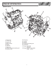
MAINTENANCE
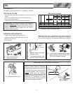
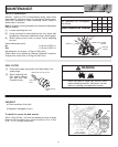
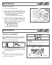
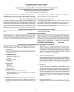
To adjust for correct tension
[1]. Loosen the 2 bolts (
A and B ).
[2]. Place a handle (or similar object) between the
alternator and engine cylinder block. Then move the
alternator towards the outside of the engine, until the
fan belt deflection conforms to the specified value.
Specified fan belt deflection:
10 to 12mm / 10kg (3/8 to 1/2 in. / 22lbs.)
[3]. Temporarily tighten the 2 bolts (
A and B ) to fix the
alternator. Then remove the handle. Check fan belt
deflection. If it is within specifications, permanently
tighten the 2 bolts (
A and B ) as given below. If not,
repeat the above adjustment procedure.
Specified tightening torque:
A : 195 kg-cm (170 in-lbs)
B : 622 kg-cm (45 ft-lbs)
Check the fan belt deflection again.
10 − 12 mm
(3/8 − 1/2 Inch)
BELT MOVEMENT
HANDLE
BELT
A
B
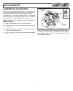
ADJUSTMENTS
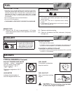
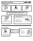
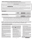
CONTROL ADJUSTMENTS
If engine is hard to start or acceleration is uneven, check
control operation and adjust if required as described
below:
[1]. Move throttle control to FAST position.
[2]. Pull choke control to CHOKE position.
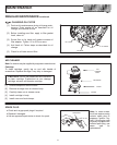
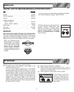
Typical throttle and choke controls
PULL
TO CHOKE
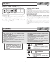
[3]. Loosen casing clamp screw, then move wire and casing
and engine choke lever in direction of arrow, until choke
valve is completely closed.
And/Or
[4]. Move wire and casing and engine throttle lever in
direction of arrow, until it touches high speed screw.
[5]. Tighten casing clamp screw.
WARNING
BEFORE PERFORMING ADJUSTMENTS OR
REPAIRS
• Disconnect spark plug wire and keep it away from spark
plug.
• Disconnect battery at negative terminal.
Choke and throttle control adjustment
CASING
CLAMP
SCREW
HIGH SPEED
SCREW
WIRE AND
CASING
CHOKE LEVER
THROTTLE
LEVER