


13
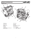
MAINTENANCE
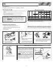
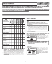
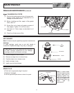
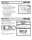
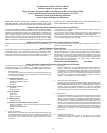
VALVE CLEARANCE
With No. 1 piston at TDC of compression stroke, check valve
clearances for cylinders shown in chart below. Rotate crank-
shaft 360° clockwise to check remaining valves. Adjust in
same order, if required.
Note: If engine is running normally, this check and adjustment
may be omitted.
[1]. Loosen adjusting lock nut.
[2]. Using a wrench to hold adjusting lock nut, adjust with
screwdriver. Determine clearance using a feeler gauge.
[3]. While holding screw driver in place, torque adjusting
lock nut.
Valve clearances (cold):
Int 0.18 mm (0.007 in.)
Exh 0.18 mm (0.007 in.)
Adjusting lock nut torque: 110 kg-cm (95 in-lbs.)
Check valve cover gasket for leakage. Replace if required.
Torque valve cover nuts to 55 kg-cm (48 in-lbs.)
Piston Position Cylinder
1 2 3
No. 1 piston at TDC, of compres-
Int
D D
No. 1 piston at TDC, of compres
sion stroke
Exh
D D
Rotate Crankshaft 360
°
clockwise
Int
D
R
o
t
a
t
e
C
ran
k
s
h
a
ft 360°
c
l
oc
k
w
i
se
Exh
D
WRENCH
SCREW
DRIVER
FEELER
GAUGE
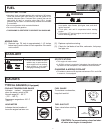
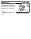
FUEL FILTER
[1]. Disconnect spark plug wires and keep away from
spark plugs.
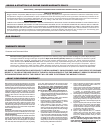
[2]. When replacing fuel
filter, ensure clamps
are tight and fuel
flows as shown.
FUEL TANK
SIDE
DIRECTION OF FUEL FLOW
CARBURETOR
SIDE
WARNING
Drain fuel tank or close fuel shut-off valve
before replacing fuel filter. Otherwise, fuel can
leak out, creating a fire/explosion hazard.
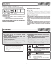
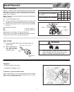
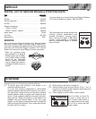
FAN BELT
♦Check condition of fan belt.
♦Replace if damaged or worn.
To check for correct fan belt tension
When 10 kg (22 lbs.) of force is pressed at center of span
between fan and alternator, there should be 10 to 12 mm
(3/8 − 1/2 in.) of belt movement.
10 − 12 mm
(3/8 − 1/2 Inch)
BELT MOVEMENT
BELT