


9
en
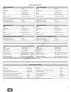
Maintenance Chart
First 5 Hours
Change oil
Every8HoursorDaily
Check engine oil level
Clean area around muffler and controls
Clean finger guard
Every 25 Hours or Annually
Clean air filter *
Clean pre-cleaner *
Every 50 Hours or Annually
Change engine oil
Check muffler and spark arrester
Every 100 Hours
Change gear reduction oil (if equipped)
Annually
Replace air filter
Replace pre-cleaner
Replace spark plug
Replace fuel filter
Clean air cooling system *
Check valve clearance **
* In dusty conditions or when airborne debris is present, clean more often.
** Not required unless engine performance problems are noted.
Carburetor And Engine Speed Adjustment
Never make adjustments to the carburetor or engine speed. The carburetor was set at
the factory to operate efficiently under most conditions. Do not tamper with the governor
spring, linkages, or other parts to change the engine speed. Ifany adjustments are
required contact a Briggs & Stratton Authorized Service Center for service.
NOTICE: The equipment manufacturer specifies the maximum speed for the engine as
installed on the equipment. Do not exceed this speed. If you are unsure what the
equipment maximum speed is, or what the engine speed is set to from the factory,
contact a Briggs & Stratton Authorized Service Center for assistance. For safe and
proper operation of the equipment, the engine speed should be adjusted only by a
qualified service technician.
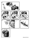
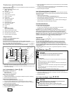
How To Replace The Spark Plug - Figure
9
Check the gap (A, Figure 9) with a wire gauge (B). If necessary, reset the gap. Install
and tightenthe sparkplug to the recommendedtorque. For gapsetting ortorque, seethe
Specifications section.
Note: In some areas, local law requires using a resistor spark plug to suppress ignition
signals. If this engine was originally equipped with a resistor spark plug, use the same
type for replacement.
Inspect Muffler And Spark Arrester - Figure
10
Running engines produce heat. Engine parts, especially muffler,
become extremely hot.
Severe thermal burns can occur on contact.
Combustible debris, such as leaves, grass, brush, etc. can catch fire.
WARNING
Allow muffler, engine cylinder and fins to cool before touching.
Remove accumulated debris from muff ler area and cylinder area.
It is a violation of California Public Resource Code, Section 4442, to useor
operate the engine onany forest-covered, brush-covered, or grass-covered land
unless the exhaust system is equipped with a spark arrester, as defined in
Section 4442, maintained in effective working order. Other states or federal
jurisdictions may have similar laws. Contact the original equipment
manufacturer, retailer, or dealer to obtain a spark arrester designed for the
exhaust system installed on this engine.
Remove accumulated debris from muffler area and cylinder area. Inspect the muffler (A,
Figure 10) for cracks, corrosion, or other damage. Remove the spark arrester (B), if
equipped, and inspect for damage or carbon blockage. If damage is found, install
replacement parts before operating.
WARNING: Replacement parts must be of the same design andinstalled
in the same position as the original parts. Other parts may not perform aswell, may
damage the unit, and may result in injury.
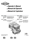
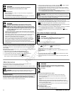
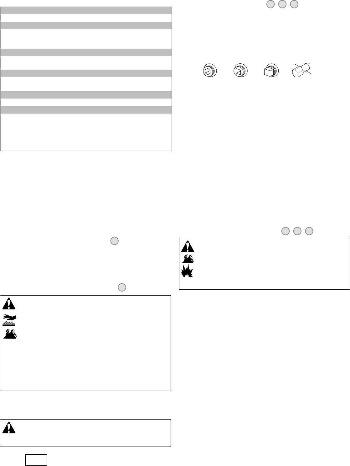
How To Change The Oil - Figure
11 12 13
Used oil is a hazardous waste product and must be disposed of properly. Do not discard
with householdwaste. Check with your localauthorities, service center,or dealer forsafe
disposal/ recycling facilities.
Remove Oil
1. With engine off but still warm, disconnect the spark plug wire (A) and keep it away
from the spark plug (Figure 11).
2. Remove the oil drain plug (B, Figure 12). Drain the oil into an approved receptacle.
Note: Any of the oil drain plugs shown below may be installed in the engine.
3. After the oil has drained, install and tighten the oil drain plug.
Add oil
Place engine level.
Clean the oil fill area of any debris.
See the Specifications section for oil capacity.
Models with oil fill cap
1. Remove the oil fill cap (D, Figure 12).
2. Pour the oil slowly into the engine oil fill (E). Fill to point of overflowing.
3. Replace and tighten the oil fill cap.
Models with short dipstick
1. Remove the dipstick (F, Figure 12) and wipe with a clean cloth.
2. Pour the oil slowly into the engine oil fill (E). Fill to point of overflowing.
3. Install the dipstick but do not screw in. Remove and check the oil level. Oil level
should be at the FULL mark (G) on the dipstick.
4. Install and tighten the dipstick.
Models with extended dipstick
1. Remove the dipstick (F, Figure 13) and wipe with a clean cloth.
2. Pour the oil slowly into the engine oil fill (E). Do not overfill. After adding oil, wait
one minute and then recheck the oil level.
3. Install and tighten the dipstick.
4. Remove thedipstick andcheck the oillevel. Itshould be at the top of the fullindicator
(G) on the dipstick.
5. Install and tighten the dipstick.
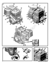
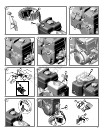
How To Service The Air Filter - Figure
14 15 16
WARNING
Fuel and its vapors are extremely flammable and explosive.
Fire or explosion can cause severe burns or death.
Never start or run the engine with the air cleaner assembly (if equipped) or the
air filter (if equipped) removed.
NOTICE: Do not use pressurized air or solvents to clean the filter. Pressurized air can
damage the filter and solvents will dissolve the filter.
The air cleaner systemuses a pleated filterwith an optionalpre-cleaner. The pre-cleaner
can be washed and reused.
Flat Air Filter (Figure 14 and Figure 15)
1. Loosen the fastener (D) that holds the cover (A).
2. Open the cover and remove the pre-cleaner (C) and the filter (B).
3. To loosen debris, gently tapt he filter on a hard surface. If the filter is excessively
dirty, replace with a new filter.
4. Wash the pre-cleaner in liquid detergent and water. Then allow it to thoroughly air
dry. Do not oil the pre-cleaner.
5. Assemble the dry pre-cleaner to the filter with the lip (G)of the pre -cleaner on the
bottom of the filter pleats.
6. Install the filter.
7. On models equipped with air filter shown in Figure 14, install the cover tabs (E)into
the slots (F).
8. Close the cover and secure with the fastener.
Oval Air Filter (Figure 16)
1. Loosen the fastener (D) that holds the cover (A).
2. Open the cover and remove the pre-cleaner (C) and the filter (B).
3. Remove the pre-cleaner (C), if equipped, from the filter. To loosen debris, gently tap
the filter on a hard surface. If the filter is excessively dirty, replace with a new filter.
4. Wash the pre-cleaner in liquid detergent and water. Then allow it to thoroughly air
dry. Do not oil the pre-cleaner.
5. Assemble the dry pre-cleaner to the filter.
6. Install the filter and pre-cleaner into the base (E) and onto stud (F). Make sure filter
fits securely into base.
7. Install air filter cover and secure with the fastener. Make sure the fastener is tight.
Not for
Reproduction