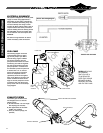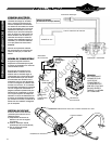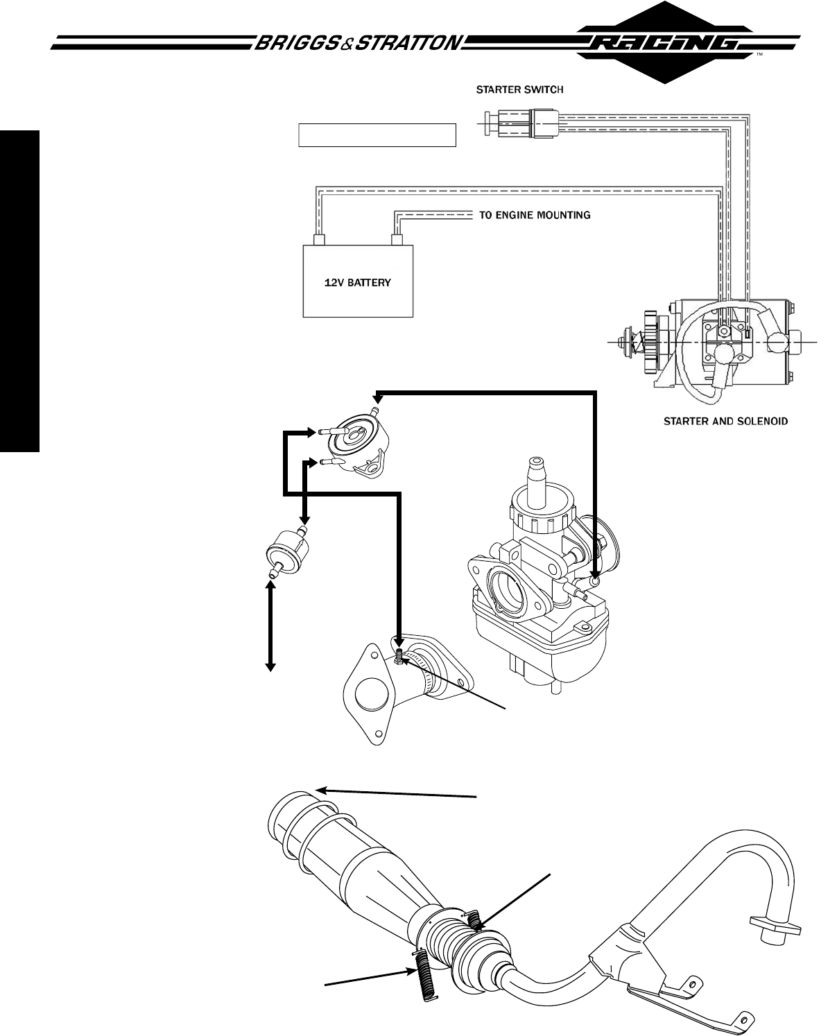
ELECTRICAL SCHEMATIC
This system is designed for a 12-volt power
supply. For most racing applications, a
high-quality, gel cell battery (determined
by your authorized sanctioning body) with
at least an 8-amp hour rating is recom-
mended. An 8mm positive battery cable is
required between the battery and starter
solenoid. Holding down the starting switch,
Part #557028, will turn the ignition OFF,
and is located on the control panel, Part
#555699.
See starter wiring schematic for starter
switch and battery cable connections.
FUEL PUMP 808656
PULSE LINE
FUEL FILTER
REMOTE
FUEL
SOURCE
PULSE FITTING
12
WORLD FORMULA ENGINES
Electric Start Wiring Diagram
FUEL PUMP
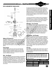
The following diagram shows the
recommended layout for attach-
ing the fuel pump to your World
Formula racing engine. A Mikuni
fuel pump is supplied. The fuel
pump should be installed as recom-
mended by your local CIK organiza-
tion. We recommend that this fuel
pump be placed in a location that
isn’t affected by heat. The pulse line
is marked with a “P” on the fuel
pump. This should be connected
with a non-collapsible fuel line
(specically made for fuel applica-
tions) to the tting on the top of the
intake manifold. The other two t-
tings on the fuel pump have arrows
to show the inlet and outlet of the
pump. Please refer to the accompa-
nying diagram.
cauTion: WE HIGHLY
RECOMMEND
THAT YOU USE A
75 MICRON FUEL
FILTER. THIS SHOULD
BE PLACED IN-LINE
BETWEEN THE TANK
AND THE FUEL PUMP.
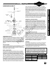
EXHAUST SYSTEM
The header pipe has been tuned
and designed to be run with the
following parts:
A) 50 mm diameter x 57 mm length
ex coupling (not included)
B) CIK approved 50/90 “2-stroke”
mufer (not provided)
C) Three (3) exhaust springs (not
provided)
EXHAUST SPRINGS
REAR KART BRACKET SUPPORT
FLEX COUPLING
Not for
Reproduction
Not for
Reproduction


