


l l l l l l l l l l l l l l l l l l l l
l l l l l l l l l l l l l l l l l l l l
l l l l l l l l l l l l l l l l l l l l
501_392c01100p01r1_us
file name date init.
BM
BMW
BMWBMW
Z3
03/98
INTRODUCTION
0110.0Ć
1997
01
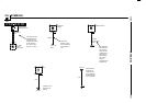
General Conventions
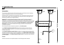
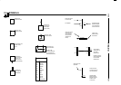
1. Switches and relays are always shown in rest position (e.g. K11).
2. A component shown in a dashed frame signifies that the component is
illustrated only in part (e.g. P90 and P91).
3. A component shown in a completely drawn frame signifies that the
component is illustrated in full (e.g. K11).
4. The dashed line between pin 8 and pin 6 of connector X293 indicates
that both pins belong to connector X293.
5. The dashed line from fuse F1 to pin 8 of connector X293 shows the
positive supply of relay K11. If required, refer to cell 0670.3 Fuse Details
at fuse F1 for the complete line progressing with plug connections, line
branches, wire colors and cross sections.
6. The dashed line with an arrow at splice X452 indicates that several wires
lead to splice X452. All lines leading to the connection are illustrated in
cell 6100.0 Central Body Electronics (ZKE). An interrupted line with an
arrow indicates that only this one wire leads to another circuit.
7. The dashed line from pin 4 of connector X293 to ground X493 shows
the ground supply for relay K11. If required, refer to cell 0670.4 Ground
Distribution at ground X493 for the complete line progression with all plug
connections, line branches, wire colors, and cross sections.
8. The interrupted line from splice X452 with an A in the open arrow is
continued on page 6160.0-02.
Termination of wire 4 VI/SW from splice X452 with a wavy line indicates
that the wire is continued on the opposite page.