


7
USING THE JUMP-STARTER
This Jump-Starter is equipped with Good/Bad Polarity Indicators. Energy will only
flow when proper connections are made to the battery and frame. Once the
connections are properly made, follow the steps below to jump-start the vehicle.
1. Turn OFF vehicle ignition and all accessories (radio, A/C, lights, connected cell
phone chargers, etc.). Place vehicle in “park” and set the emergency brake.
2. Make sure the unit is disconnected from all charging power sources.
3. Remove jumper clamps from clamp tabs. Connect the RED clamp first,
then the BLACK clamp.
4. Procedure for jump-starting a NEGATIVE GROUNDED SYSTEM (negative
battery terminal is connected to chassis) (MOST COMMON)
4a. Connect POSITIVE (+) RED clamp to vehicle battery’s POSITIVE terminal.
4b. Connect NEGATIVE (–) BLACK clamp to chassis or a solid, non-moving,
metal vehicle component or body part. NEVER CLAMP DIRECTLY TO
NEGATIVE BATTERY TERMINAL OR MOVING PART.
5. Procedure for jump-starting POSITIVE GROUND SYSTEMS
Note: In the rare event that the vehicle to be started has a POSITIVE GROUNDED
SYSTEM (positive battery terminal is connected to chassis), replace steps 4a
and 4b above with steps 5a and 5b, then proceed to step 6.
5a. Connect NEGATIVE (–) BLACK clamp to vehicle battery’s NEGATIVE terminal.
5b. Connect POSITIVE (+) RED CLAMP to vehicle chassis or a solid, non-
moving, metal vehicle component or body part. NEVER CLAMP DIRECTLY
TO POSITIVE BATTERY TERMINAL OR MOVING PART.
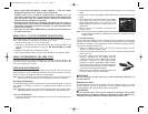
6. When clamps are connected properly, press the Power Button on the back of the
unit (see the diagram on page 3) to turn the unit ON.
7. Turn ON the vehicle ignition and crank the engine in 5-6 second bursts until
engine starts.
8. Press the Power Button on the back of the unit once more to turn the unit OFF.
9. Disconnect the NEGATIVE (–) engine or chassis clamp first, then disconnect the
POSITIVE (+) battery clamp.
FOLLOW ALL SAFETY INSTRUCTIONS FOUND ON PAGES ii THRU iv OF
THIS OWNER’S MANUAL.
CAUTIONS
• If the Reverse Connection LED on the front of the unit lights (and the Digital Display
shows “F06”) after clamps are connected to vehicle battery, polarity is wrong.
Reverse the clamp connections.
• If vehicle fails to start, turn OFF the vehicle ignition, turn OFF the Jump-Starter,
disconnect the jump-start system’s leads and investigate why the engine did not
start.
• Recharge this unit fully after each use.
WARNINGS
• Make sure the unit is disconnected from all charging power sources
before beginning the jump-starting procedure.
• This power system is to be used ONLY on vehicles or boats with
12 volt DC battery systems.
6
Alternator Check
Part 1
No Load (Turn OFF all vehicle’s accessories): The battery must be fully charged
before testing the alternator. Run the engine long enough to achieve
normal idle speed and verify there is a no-load voltage.
1. Press Alternator Check to start the check.
2. Alternator Good LED will light to indicate the alternator is good, or F07
will display if alternator output voltage is out of typical operation range.
3. Press Alternator Check again to stop the test.
Part 2
Under Load (Accessories ON): Next, load the alternator by turning on as many
accessories as possible (except for A/C and DEFROST)
1. Press Alternator Check to start the check.
2. Alternator Good LED will light to indicate the alternator is good, or F07
will display if alternator output voltage is out of typical operation range.
3. Press Alternator Check again to stop the test.
If the first alternator check indicates a good alternator and the second indicates the
alternator is bad, the problem could stem from: loose fan belts, an intermittent diode
failure or possibly bad connections between the battery and alternator and/or ground.
Notes: The Battery Charge Level Button button is disabled in Alternator Check
mode.
F07 may display because someone has added a number of accessory loads
on the charging system, thereby increasing current demand from the
alternator. MAKE SURE THAT THE ALTERNATOR IS RATED TO SUPPORT THE
APPLICATION.
This check may not be accurate for every make, manufacturer and model of
vehicle.
Check only 12 volt systems.
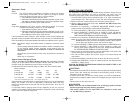
Approximate Charging Times
The
2/6/10 Amp 12 Volt Smart Battery Charger
will automatically adjust the
charge rate as the battery becomes charged and stop when the battery is fully
charged. Deep cycle batteries may require longer charging time.
For estimates of the time it takes to charge a battery, refer to the following table.
Percent of charge
in battery 75% 50% 25% 0%
at 2 amp rate 7 HRS 14 HRS NR* NR*
at 6 amp rate 2.5 HRS 4.7 HRS 7 HRS 9.2 HRS
at 10 amp rate 1.4 HRS 2.8 HRS 4.2 HRS 5.5 HRS
*NR = Not recommended at 2 amps — use a higher charge rate.
The times shown in the table above are approximate and refer to a 50 Ah automotive
battery. For example, a 50 Ah (12 volt) battery is discharged (50%). How long
should it be charged at the 6 amp rate? See the chart above under “50%” and “at
6 amp rate.”
In most cases, battery charging times will vary depending on the size, age and
condition of the battery. Smaller batteries should be charged at a lower rate (2 amps)
and an extra hour added to charge time.
VEC012BBD_ManualEN_020106 2/1/06 3:13 PM Page 6