


Part No 812379 Form No F060711B
6
DL12/13/14/18 Owner’s Manual
ASSEMBLY
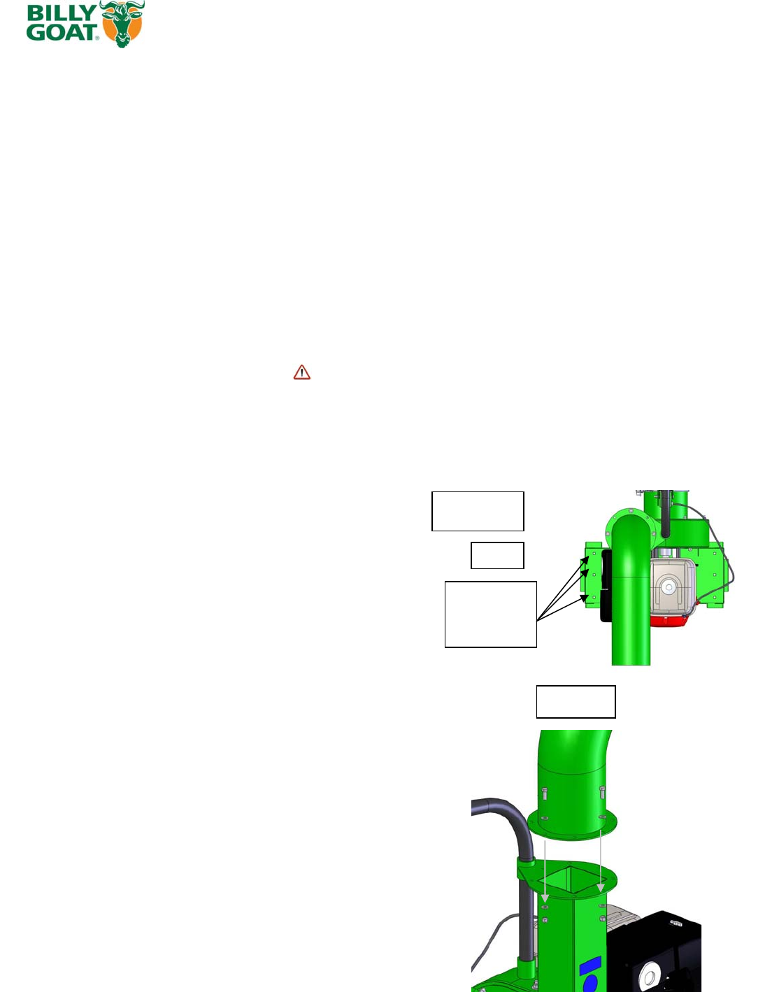
MOUNTING
MOUNTING: Main unit
GENERAL: Unit must be securely mounted to a trailer, truck bed,
hanging brackets, or other similar surface before use. Do not use this unit
in a freestanding position. Unit is not stable until it has been secured in
place.
Secure unit by bolting through the base of the unit and through the
mounting surface using 3/8" dia. bolts, with washers and locking nuts
(see fig. 1)
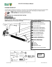
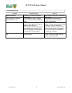
MOUNTING: Exhaust elbow
Note: this process is easier with two people, one to support the exhaust
elbow and one to attach plates and hardware.
1) Remove the bolts (item 50), washers (item 51), and nuts (item 41) from
the parts bag.
2) Place the elbow on top of the housing chute and line up with the holes
in the elbow with the housing in the desired position you want the exhaust
to go.
3) Secure the elbow to the housing with the hardware provided. Make
sure the hardware is properly tightened.
Fig. 1
Typical on
both
sides
Step 1&2
Mount with
these holes
on both sides
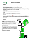
1. SECURELY ATTACH unit to the bed of a truck, trailer, or use the hanging brackets, so that the exhaust discharges into an
enclosed container.
NOTE: This unit must be securely mounted to the bed of a truck or to a trailer before operating.
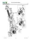
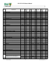
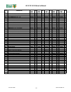
See page 14 for parts diagram to assemble
2. ATTACH hose to housing intake, using hose quick clamp (item 8) making sure to place the safety switch under the clamp (see
interlock page 12. Then slide the hose onto the housing intake and place the shut off switch under the clamp. Make sure the shut off
switch is pressed in or the vacuum will not start, and clamp the hose to the intake.
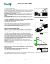
3. ASSEMBLE nozzle handle (item 11), to nozzle (item 10), using screws (item 60), fender washers (item 56), washers (item 57)
and lock nuts (item 43).
4. ATTACH assembled nozzle to hose using hose clamp (item 9). Before tightening hose clamp, position nozzle handle upward
when hose is stretched to prevent twisting load on hose assembly during operation.
5. ATTACH the hose boom (item 5) by sliding the boom through the ring on the top of housing and resting it in the cup on the top of
the housing.
6. ASSEMBLE hose band (item 13) around hose and secure chain between flanges of the hose band using capscrew (item 52),
washers (item 54), and lock nut (item 53). To adjust the hose boom height see page 11)
7. SECURELY ATTACH exhaust elbow (item 4) to the housing (see MOUNTING on page 10) with the hardware located on the
exhaust chute.
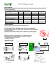
8. INSTALL BATTERY (Electric Models Only)
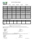
Due to the location of the battery it is recommended that only the specified
battery be used on the DL1401SE and DL1801VE. This is due to the heat generated by the muffler and the location of the battery.
Using the wrong size battery could result in premature failure, damage to unit or personal injury. The battery needs to be within the
specification list on page 3. The U1 group or equivalent is recommended for the DL18VE (SEE PAGE 3 FOR BATTERY
SPECIFICATIONS)
9. (Electric Models Only) Attach the battery cables to the battery and secure it to the unit with the hold down strap.