


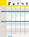

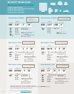


Blank = K80L: Terminal-wired
K50L: 2 m
Q = 5-pin integral QD
QP = 5-pin Euro pigtail QD
A1 = Steady tone
A2 = Pulsed tone
AL1 = Loud steady tone
P = PNP (Sourcing)
N = NPN (Sinking)
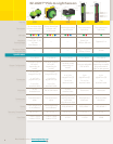
Color Audible Color
Housing C1 C2 Alarm C4 Input Connection
G = Green
R = Red
Y = Yellow
B = Blue
W = White
K50L
K80L
K50L G R A2 Y P QP
Audible
Blank = 2 m
Q = 4-pin integral QD
QP = 4-pin Euro pigtail QD
P = PNP (Sourcing)
N = NPN (Sinking)
Color*
Housing C1 C2 C3 Input
†
Connection
G = Green
R = Red
Y = Yellow
B = Blue
W = White
X = No color
K50LD
K50LD G R Y P QP
Daylight Visible
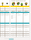
G = Green
R = Red
Y = Yellow
B = Blue
W = White
X = Place holder
1 = Micro
Programmed
Blank = Terminal-wired
Q = 5-pin Euro pigtail QD
QP = 5-pin Euro pigtail QD
Blank = 4 segments or
no segments
H = Horizontal split
TH = Top half
P = PNP (Sourcing)
N = NPN (Sinking)
Segment Color*
Housing Configuration C1 C2 C3 C4 Function Input Connection
4 = 4 segments
3 = 1 half & 2 qtr.
2 = 2 halves
1 = Entire area
K80L
K80L 4 - G R Y B 1 P Q
Segmented
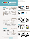
EZ-LIGHT™
Hookup Diagrams
Hookup Diagram: HK03
Online Data Sheet: P/N 132728
Hookup Diagram: HK03
Online Data Sheet: P/N 135242
Hookup Diagram: HK01
Online Data Sheet: P/N 137330
11
More information online at bannerengineering.com
4
3TH
2H
1
*For less than 4 colors, use X as a model placeholder (example, K80L2HGRXX1PQ = )
* For single color models with full brightness, use XC2X in model number (example, K50LDXGXPQP).
For single color models with intensity control of one color, use same color for C1, C2, C3 (example, K50LDGGGPQP).
†
1-color models are PNP/NPN selectable.
HK02
• General Purpose (AC)
KEY
1 = Brown
2 = White
3 = Yellow*
4 = Black
5 = Blue
* = Not Used
HK01
• General Purpose (DC)
• Daylight Visible
KEY
1 = Brown
2 = White
3 = Blue
4 = Black
PNP NPN
4-Pin
Euro
5-Pin
Micro
5-Pin
Euro
8-Pin
Euro
4-Pin
Euro
HK03
• 3- or 4-color, Multi-Function
• Segmented
• Audible
KEY
1 = Brown
2 = White
3 = Blue
4 = Black
5 = Gray
PNP NPN
HK04
• 5-color, Multi-Function
KEY
1 = White
2 = Brown
3 = Green
4 = Yellow
5 = Gray
6 = Pink
7 = Blue
8 = Red
PNP NPN
HK05
• Sensor Emulator
KEY
1 = Brown
2 = White
3 = Blue
4 = Black
PNP NPN
*K50L and K80L voltage 18-30V dc
*K50L and K80L voltage 18-30V dc
NOTE: Hookup diagrams are for LED ON steady.
See data sheet for LED function information.
NOTE: Hookup diagrams are for LED ON steady.
See data sheet for LED function information.
NOTE: For reference only; confirm model number with
Banner as some configurations are not available.
*No color: General Purpose and Daylight Visible only
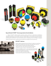
Note: Many other
colors are available
G R Y B W X
*