


Installation Guide P. 3
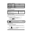
4. Relock
• If you unlock the doors with the remote transmitter, but do not open any door or trunk within 60 seconds,
the doors will automatically relock.
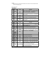
Harness Description
5 PIN HARNESS
WIRE Wire colour
Function Description
1 BLACK
(-) CHASSIS GROUND
INPUT
This wire must be connected to bare, unpainted metal (the
chassis or true body ground). It is preferable that you use a
factory ground bolt rather than a self-tapping screw.
2 RED +12V POWER INPUT
Connect to the +12 V power feed of the vehicle, at the Ignition
harness. The source wire should have +12 V without Ignition
key in the cylinder.
3 GREY
(–) HOOD SWITCH
INPUT
Connect this wire to the installed hood pin switch supplied.
4
YELLOW /
BLACK
PARKING LIGHT
INPUT
Connect to ground or +12 V for polarity control on pin #5
5 YELLOW
PARKING LIGHT
OUTPUT
Connect to parking lights circuit of the vehicle. This wire will
give either a positive or a negative output; depending on the
polarity of pin #4.
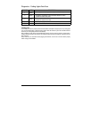
12 PIN HARNESS
WIRE Wire colour
Function Description
1 PINK
(+) IGINITION
INPUT
Connect to the Ignition wire of the vehicle. The source wire
should have +12 V with the ignition key in the IGNITION ON
(RUN) and CRANK positions.
2 PURPLE NA
3
GREY /
Light BLUE
(-) TRUNK INPUT Connect to the wire that tests ground with trunk open
4
GREY /
GREEN
(-) NEGATIVE
TRIGGER INPUT
When connected to the wire that provides ground when remote
started this input will cause the alarm system to ignore the
ignition and shock sense while running by remote start.
(Trigger alarm input — selected by Default)
5
WHITE /
RED
N/A
6
WHITE /
BLUE
N/A
7
GREY /
BLACK
(-) DOOR TRIGGER
INPUT
Connect to the wire that tests ground with a door open. Note:
This wire should monitor all the doors.
8
GREY /
RED
(+) DOOR TRIGGER
INPUT
Connect to the circuit of the car giving +12 V when a door is
opened (usually the dome-light circuit).
9
BLACK /
Light BLUE
(–) AUX 1
output
This wire will provide 500mA ground output depending on the
configuration of Mode 1, Function 5 (see programming options)
10
BLACK /
BROWN
(–) AUX 2
output
This wire will provide 500mA ground output depending on the
configuration of Mode 1, Function 4 (see programming options)
11
BLACK /
GREEN
(–) AUX 3
output
This wire will provide 500mA ground output depending on the
configuration of Mode 1, Function 3 (see programming options)
12
BLACK /
PINK
(–) Zone 2 Disable
Output (armed output)
This wire will provide a constant 500mA output when the
system is armed (locked by remote control). It can be
connected to an external starter interrupt relay.
This wire should be connected to a single pole double-throw
relay: this wire will connect to pin 85 on the relay, and pin 86
will be connected to the ignition wire.