


3
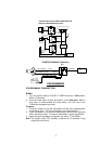
(RELAY REQUIRED)
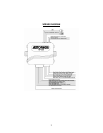
8. GRAY ...2ND CHANNEL OUTPUT
2. WHITE...DOME LIGHT / 3RD CHANNEL OUTPUT
7. ORANGE...STARTER INTERUPT OUTPUT
(RELAY REQUIRED)
5. GREEN...NEGATIVE DOOR TRIGGER (-) INPUT
6. YELLOW...IGNITION INPUT
3. VIOLET...POSITIVE DOOR TRIGGER (+) INPUT
1. BROWN/WHITE...(-) HORN OUTPUT
4. BLUE...NEGATIVE INSTANT (-) INPUT
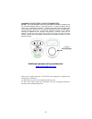
H1: MAIN 5 PIN WIRE HARNESS:
15A Fuse
5. Red Wire: +12V To Constant Battery Source
4. Brown Wire: Positive output To
3. Black Wire: Ground to Vehicle FRAME
2. White Wire: Parking Light Relay Output
1. Red / White Wire: Parking Light Relay input
Siren
H2: 8 PIN MINI CONNECTOR WIRE HARNESS:
*
Siren and Starter Kill relay optional
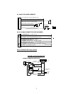
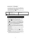
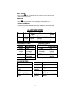
DOOR LOCK DIAGRAMS
+12V
Master Door
Lock Switch
X
X
Splice
Splice
Cut the Existing
Lock Wire
To Door
Lock
Motor
To Slave Door
Lock switches
Cut the Existing
Unlock Wire
3 Pin Plug
To Alarm
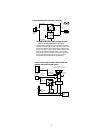
5-WIRE ALTERNATING DOOR LOCK
30
86
87a
85
87
30
86
87a
85
8
7
+12V
Green Wire
Blue Wire