


5
DASH MOUNTED LED
2PIN White Plug w/2 Wires; Red & Blue
The Red & Blue wires in the 2PIN mini white connector control the anode and cathode of the dash mounted LED.
Route the twin lead Red and Blue wires from the LED to the control unit and plug the two pin connector into the
mating white mini connector shell of the control module. Do not force the connector, it will only plug in one way.
VALET/PROGRAM/MANUAL OVERRIDE SWITCH
2PIN Blue Plug w/2 Wires; Black & Gray
The Black & Gray wires in the 2PIN blue connector are the ground supply and Valet/Program input of the PRO
9845 unit. When the Gray wire is grounded, under certain conditions, the unit will enter the valet mode. When the
Gray wire is sequentially grounded under other conditions, the unit will enter the various program modes. Route
the Black and Grey wires from the Valet/Program/Manual Override switch to the PRO 9845 unit and plug the blue
2PIN connector into the mating blue connector shell of the PRO 9845 control module. Do not force the connector,
it will only plug in one way. Note: Please refer to the section; "Programming System Features" shown later in this
installation guide to learn the operation of the valet/program/manual override switch.
POWER DOOR LOCK HARNESS
3PIN White Plug w/3 Wires; Red, Green, and Green/Black
The connection of the power door lock/unlock wires has already been explained. Route the Red, Green, and
Green/White wires to the PRO 9845 unit and plug the white 3PIN connector into the mating white three pin
connector shell of the PRO 9845 control module. Do not force the connector, it will only plug in one way.
TRANSMITTER PROGRAMMING:
The transmitters supplied with the PRO 9845 are pre-programmed at the factory to provide the following function:
Button 1, pressed and released quickly = Lock & Unlock w/Siren or Horn Chirps
Button 1, pressed for ~ 2 second = Lock & Unlock w/o Siren or Horn Chirps
Button 1, pressed for ~ 3 seconds = Engage/Disengage Panic Mode
Button 2, pressed for ~ 3 seconds = Channel 2 Output
Buttons 1 & 2, pressed and HELD = Channel 3 Output
If you desire to have the transmitters operate differently from this factory configuration, please refer to the separate
Transmitter Programming Guide that came with the PRO 9845 system.
PROGRAMMING FEATURES:
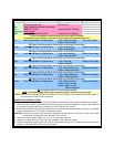
There are seven (7) Programmable Features on the PRO 9845 system. Study the list below, keeping in mind the
features and their defaults, (how it comes programmed from the factory), and decide how best to program the
PRO 9845 for your particular installation.
Programmable Features:
Features 1 Chirp 2 Chirp 3 Chirps Default
First Passive Arming Active Arming Active Arming
Second Ignition D/L ON Ignition D/L OFF Ignition D/L OFF
Third Ignition D/UL ON Ignition D/UL OFF Ignition D/UL OFF
Fourth Chirps ON Chirps OFF Chirps ON
Fifth Passive D/L Active D/L Active D/L
Sixth Siren Output Horn Output Horn Output
Seventh 800ms D/L Pulse 3.5 Sec. D/L Pulse 800ms D/L Pulse 800ms Door Lock
Double 800ms D/UL Pulses
To Program These Features:
Entering the Programming Mode involves operating the Ignition Switch and the Valet/Program/Manual Override
Switch in a particular sequence. This sequence is very time dependent, in other words it must be performed
quickly in order for you to enter the mode. This sequence is also only one step different from the Transmitter
Programming Mode, so make certain you perform the sequence properly.