


Page 4
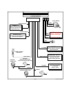
2 Dark Green w/ White Trace Wires : Entry Illumination
The dark green w/ white trace wires provide the entry lighting, and flash the vehicle’s dome light while the
alarm is sounding. These are NO ( normally open ) and COM ( common ) contacts of an on board, 10 Amp
maximum relay.
Connect one of the dark green w/ white trace wires to the wire in the vehicle that turns on the interior courtesy
light. Connect the other dark green w/ white trace wire to either chassis ground if the vehicle switches ground
to the courtesy lights, or a fused + 12 volt constant battery source if the vehicle switches 12 volts to the
courtesy lights.
NOTE : When wiring this feature in vehicles with factory equipped delay lighting circuits, it is best
to connect to the output of the timer which feeds the dome light, rather than at the door
switch. This will ensure that the dome light pulses when the alarm is triggered.
White w/ Black Trace Wire : Positive Output to Siren
Route this wire through a rubber grommet in the firewall, and to the siren location.
Connect the white / black wire to the positive wire of the siren. Secure the black ground wire of the siren to
chassis ground.
Mini 9 Pin Edge Connector :
Light Green Wire : ( - ) Instant Trigger Zone 1
This is an instant on ground trigger wire. This wire ( zone ) should be reserved for connection to optional
ground output trigger devices such as motion and / or shock impact sensors.
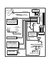
White w/ Blue Trace Wire : Headlight Output - Arm & Disarm
The white w/ blue trace wire is provided to control the optional headlight illumination feature of the system.
This is a transistorized, low current ( 300 mA ) output, and should only be used to drive an external relay coil.
This wire provides a 30 second ground signal whenever the system is remotely armed or disarmed.
Connect the white w/ blue trace wire to terminal 86 of the AS 9256 relay ( o r an equivalent 30 Amp automotive
relay ), and connect relay terminal 85 to a fused + 12 VDC battery source. Connect relay terminal 87 to one
of the low beam headlight wires in the vehicle, and connect relay terminal 30 to either chassis ground or a
fused ( 15 Amp Min)+12VDCbattery source, depending on the polarity of the headlight circuit in the
vehicle.
Yellow Wire : + 12 VDC Ignition Source
Connect this wire to a source that is live when the key is in the on and crank positions. Be sure that this
source is off when the key is in the off position.
Purple Wire : + Door Trigger
If the vehicle’s door courtesy light switches havea+12volt output when the door is opened ( some Fords and
some Imports ), you must connect this wire to the positive output from one of the door switches. In most
cases, the purple wire will only need to be connected to one door switch, no matter how many doors the
vehicle has.
WARNING : Do not use the purple wire if the vehicle has ground output type door switches. ( see Brown
Wire).
Brown Wire : - Door Trigger
If the vehicle’s courtesy light switches havea(-)ground output when the door is opened ( GM and most
Imports ), you must connect this wire to the negative output from one of the door switches.
WARNING : Do not use the brown wire if the vehicle has + 12 volt output type door switches. ( see Purple
Wire ).
Dark Green Wire : ( - ) Instant Trigger Zone 2
This is an instant on ground trigger wire. It must be connected to the previously installed hood and trunk pin
switches.