


128-6533
23 of 24
23
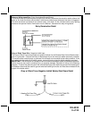
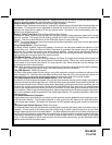
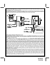
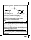
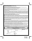
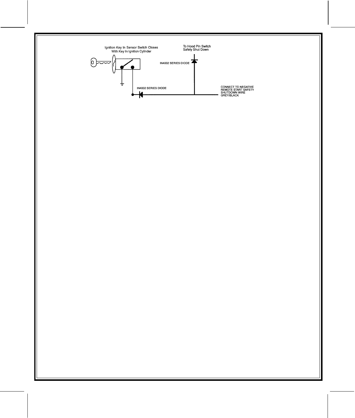
METHOD 2
To connect to the key in sensor circuit as shown for method 2:
A. Locate the control wire that connects the drivers door pin switch to the key in sensor switch.
B. Cut this wire and connect the ignition cylinder side to chassis ground.
C. Locate the key in sensor switch wire that connects the chime module to the ignition cylinder .
D. Cut this wire and connect the ignition cylinder side to the Remote Start Negative Safety Shut down Wire
Gray/Black, using a 4002 series diode as shown above.
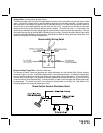
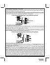
NOTE: A second 4002 series diode may be required to maintain the integrity of the hood open, shut down
circuit. If this is the case, it must be installed as shown in the diagram above. The anode (Non Striped) side
must be connected to the Gray/Black wire of the Remote Start Unit. The cathode (Striped) side must be
connected to the hood pin switch. If the hood pin switch is also used for an alarm trigger input, be certain to
use the dual diode assembly packaged with the Audiovox Remote Start Unit as shown in this installation
guide. (Page 9)
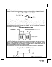
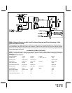
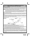
AFTER THE CONNECTION OF THE NEUTRAL START SAFETY WIRE AS INDICATED IN ANY OF THE
PREVIOUS ALTERNATE CONFIGURATIONS, THIS CIRCUIT MUST BE TESTED FOR OPERATION.
Retest by following the steps outlined in the NEUTRAL START SAFETY TEST shown in this manual.
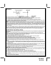
COMPLETING THE INSTALLATION:
After you have confirmed the operation of the Audiovox Remote Start unit and tested all the safety features of
the system:
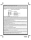
NOTE: This unit has the ability to learn the dome light delay time, up to 60 seconds. If the vehicle has
delay interior lights, and you wish to avoid three chirp, defect zone, indication normally associated with this
type of interior light, we suggest you learn the interior light delay.
To learn the light delay, start with all doors closed:
(1) Use the transmitter to Lock / Unlock / Lock / Unlock / Lock / Unlock / Lock, the system.
The LED turns on solid to confirm the system entered the learn mode.
(2) Immediately open and close the door of the vehicle to initiate the dome delay.
The unit will monitor the door trigger input Positive, (Purple), and Negative, (Brown) when active.
When the dome light turns off, the unit will add 2 seconds then exit the learn mode.
(3) The LED will begin flashing the Armed indication indicating the unit has exited the learn mode and is
armed.
1. If you have not done so already, place the red rubber handle cover over the handle of the control switch for
ease of identification. This will allow your customer to distinguish the Remote Start control switch from the
program switch.
2. Mount the control module up and behind the dash securing it in place with cable ties or screws. Be certain
that the chosen mounting location will not inhibit any of the controls of the vehicle.
3. Securely harness and tie all wiring up and away from all hot and moving parts that they may come in
contact with under the dash board or in the engine compartment areas.
CAUTION: Particularly avoid the area around the steering shaft and column, as wires can wrap around these
mechanisms and impair the safe operation of the vehicle.
4. Apply the Caution Labels supplied with this kit to a conspicuous area in the engine compartment. Make
sure to clean the surface before affixing the label.
5. Check the vehicle's wipers, lights, horn, etc.... to insure proper operation.
6. Replace all panels that were removed during installation, and retest the system.
7. Explain all activated features and safety systems associated with Remote Start Unit installed to the
customer.
8. Place the Valet Switch Tag and or the Remote Start Control Switch Tag on their respective switches and
point these out to the customer.