


TYPICAL CHRYSLER APPLICATION: (See Figure 5)
IMPORTANT! It will be necessary to purchase separately the AK-95-CPC Chrysler power/speaker wiring adapter and the
AK-94-GMMB antenna adapter for installation into all Chrysler/Dodge/Plymouth and Jeep vehicles.
1. Radio Preparation
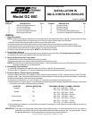
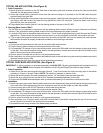
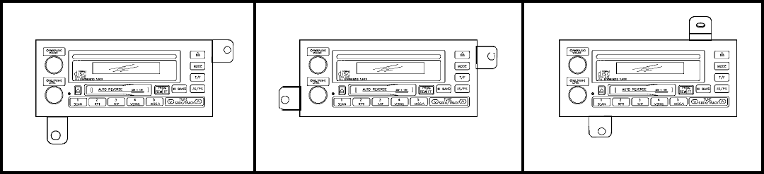
1) Select two of the three mounting tabs provided (Items 6, 7 and 8) and match the radio mounting style of the vehicle
according to Figures 1 through 3 below. NOTE: Tab number is stamped on bottom of tab.
2) Attach the mounting tabs to the radio chassis with the four 1/4" hex head screws provided (Item #9).
3) Attach the 14-pin connector from the AK-95-CPC harness (purchased separately) to the radio.
4) Plug the AK-94-GMMB antenna adapter cable (purchased separately) into the antenna socket on the radio.
2. Installation
1) Attach ring lug on ground wire (black w/white stripe) from radio side harness along with the vehicle side grounding strap
to the rear of the radio chassis using the short quickie bolt (Item #2) and the flange nut (Item #4) provided.
2) Connect mating side of AK-95-CPC harness to vehicle side wiring harness.
3) Connect the vehicle antenna cable to the radio antenna adapter cable.
4) If a compatible CD changer is to be used with this radio, connect the DIN cable from the changer to the mating socket
on the radio. If an external amplifier will be used for the rear speakers, connect the low-level output RCA leads from the
radio to the low-level inputs on the amplifier.
5) Perform a brief functional test of radio to verify proper performance.
6) After verification, turn off ignition switch and install into sub-dash of the vehicle using either the two 10 mm hex head
screws (Item #10) provided or the existing factory hardware.
7) Re-assemble dash using reverse of the disassembly procedure.
TYPICAL GM APPLICATION: (See Figure 4)
1. Radio Preparation
1) Match quickie bolt locations on the GC-600 radio to the factory radio bolt locations and snap the short quickie bolts
(Item #2) into the appropriate locations.
2) Attach the original factory brackets or those from the radio mounting kit (if required) to the GC-600 radio using the
supplied flange nuts (Item #4).
3) Some vehicle applications incorporate a rear mounting support. Match the rear quickie bolt on the GC-600 radio to the
rear factory radio bolt location and snap the long quickie bolt (Item #3) into place. Thread the plastic rear bushing
(Item #5) fully onto the quickie bolt.
4) Plug supplied wire harness (Item #1) into the mating socket on the rear of the GC-600.
2. Steering Wheel Control (SWC)
The GC-600 can be operated in conjunction with the steering wheel controls offered on many Chevrolet and Pontiac
vehicles. If the vehicle has steering wheel controls, follow the steps below for proper operation.
1) Locate the SWC wire on the vehicle side radio harness. This is usually a light green wire in most Chevrolet and Pontiac
applications. Please consult the vehicle's service manual if you are not certain of the SWC wire location and color.
2) T-Tap or splice the single blue w/red stripe wire from the radio into the SWC wire from the vehicle side radio harness.
Make certain the splice is properly routed and insulated to avoid shorting to sub-dash.
3. Installation
1) Connect the wiring harness from the radio to the vehicle side radio harness.
2) Plug the factory antenna cable into the antenna socket on the radio.
3) If a compatible CD changer is to be used with this radio, connect the DIN cable from the changer to the mating socket
on the radio. If an external amplifier will be used for the rear speakers, connect the low-level output RCA leads from the
radio to the low-level inputs on the amplifier.
4) Perform a brief functional test of radio to verify proper performance.
5) After verification, turn off the ignition switch and fasten the radio to the sub-dash using the mounting hardware previously
removed from the factory radio.
6) Re-assemble the dash using the reverse of the disassembly procedure.
TAB #2
TAB #1
TAB #2
TAB #2
TAB #2
TAB #3
FIGURE 1
FIGURE 2 FIGURE 3
STANDARD MOUNTING CONFIGURATION
"JA" MOUNTING CONFIGURATION
"JZ" MOUNTING CONFIGURATION