


Step 5: Tape the strip around the drive shaft at the location chosen for the magnets. Remove backing paper
from magnets andpress one magnetnext to each markon the paperstrip (place magneton the cleaned drive
shaft, not the paper). Be sure magnet tabs are lengthwise on the shaft. See Figure 7.6.
Step 6: While rotating the shaft, carefully snap one wire into one set of magnet slots. Loosely wrap the wire
to hold it in place. Snap the second wire into the remaining slots making sure the ends are nearly opposite
the first wire, as shown in Figure 7.6 or 7.11.
Step 7: Carefully pull wires tight, and wrap with a pair of pliers. Pull down as you twist to avoid breaking the
wire. Now take the loose ends and wrap through the opposite wire and twist to remove any excess slack,
see Figure 7.6. The wires actuallyhold the magnets onto the drive shaft. The double-faced tape is used only
to temporarily hold the magnets until the wire is attached.
Step 8: Spin the drive shaft by hand and check for any clearance problems. Remember that the drive shaft
position will change with the suspension. See Figure 7.3.
SPEEDSENSOR INSTALLATION
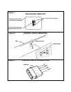
Step 9: Assemble the speed coil and bracket with nut and lock washer. Use of mounting bracket will be
determined by the specific installation. Refer to Figures 7.5 and 7.10 . In some cases installation may be
easier if the bracket is bent or cut to a specific shape.
Step 10: Determining thelocation for the speedsensor/bracket assembly, thespeedsensor must be pointing
directly at the centerline of the shaft and there should be 3/8" (10 mm) clearance between the speedsensor
and the magnets. See Figures 7.9.
Step 11: Use the bracketas a template to mark andcenter punch two hole locations. Drill two 3/16" diameter
holes. Mount the speedsensor/bracket assembly using two 1/4" x 3/4" sheet metal screws. Be sure bracket
is mounted so it will not vibrate during vehicle movement.
CAUTION: Before drilling any holes, make sure there are no parts which may be damaged on the other side
of the metal. Double check for any wiring harness which might be easily damaged by the drill bit.
NOTICE: If the speed coil is closer than 1/4", there is a possibility that the magnets will strike the coil. If the
coil is more than 1/2" from the magnets, the cruise control may not function properly.
Step 12: Route the black and gray paired wires to the speedsensor and attach to the terminals. (It does not
matter which way the wires are attached).
NOTE: Make sure thesewires are not runnext to hot engine partsor electrical items suchas spark plug wires
or ignition systems, as an interference could occur causing the cruise control to surge.
NOTE: This magnet kit cannot be used on Hondas.