


4. Determine where the sensor wires will enter into the trunk area or passenger compartment. Many vehicles have a factory
grommet to allow routing of wires from the outside to the inside of the vehicle. If you are drilling a hole through a metal body
panel to route your sensor wires into the trunk/cargo area, be sure to coat the holes edges with Zinc Galvanizer.
5. Feed the sensor wires through the factory grommet or other opening into the vehicle for connection to the control module
(e.g., into the cab of most trucks or the trunk of passenger cars). Finish by fitting the hole with a rubber grommet, or by
using automotive grade silicone to prevent moisture from entering the vehicle.
NOTE: Once the wires are passed through, ensure that you have the right amount of slack needed to route to the control
module. Make sure that the sensor wires will not be pinched by moving parts or panels.
6. Cable tie the sensor wires behind the bumper, away from any area that is close to the exhaust system or moving suspen-
sion parts. Do not pull or yank on the sensor wire were it exits the sensor shaft, as you may damage the inner connec-
tions.
7. Cover the sensor wires with split-loom for a factory appearance.
Mounting the Adjustable Piezo Speaker and Optional LED
The piezo speaker has three adjustment positions: Hi, Low and Off. Therefore, you need to mount the piezo speaker to the
vehicle interior where it can be easily accessed for adjustment.
1. Route the plugs for both the speaker and optional LED to the area where you will install the control module. Make sure that
they will not be pinched by any panels or moving parts.
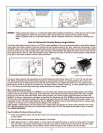
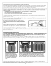
2. Clean the piezo speaker back mounting area with the supplied alcohol pad, remove the backing strip from the Velcro and
firmly press the velcro pad onto the speaker back; then position the speaker into place on any fibrous cloth surface, or
mount with the screws supplied.
3. Attach the optional LED using the supplied brackets and double-sided adhesive foam pad , making sure it is in view
through the rear-view mirror, or rear center of the vehicle drivers line-of-sight.
NOTE: Do not mount speaker or optional LED in direct sunlight.
Mounting the control module.
Determine a dry place inside the vehicle (which will be out of the way) to mount the control module (e.g., behind an inner body
panel), making sure that all wiring will reach it’s intended location.
1. Plug the sensor wires, piezo speaker and power harness into the control module before mounting.
NOTE: The control module is pre-fitted with 3M Velco for mounting.
2. Clean the pre-selected mounting area with the alcohol pad provided to ensure good adhesion.
3. When surface is dry, peel off the backing of the Velco pad and stick the control module in place.
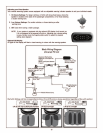
Connecting the Power Harness to the vehicle:
Determine where the reverse light wire is located. There are two methods of quickly and easily locating the reverse light power
wire:
CAUTION: Set the parking brake. The ignition key must be in the on position, but do not test with the engine running.
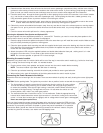
1. The first method is to actually remove the tail light housing from the vehicle. On many vehicles,
this can be done by simply removing 2 to 3 screws or bolts, and using light finger pressure.
to remove the assembly. Once the tail light housing is removed, examine where the wires plug in
to the back of the light housing. The target wire will have +12 volts when the vehicle is in the
reverse position, and 0 volts in any other gear position.
2. The second method also involves the use of a 12 volt multimeter. Probe the appropriate wiring
harness which heads toward the reverse light connector of the vehicle, looking for the wire which
carries +12 volts when reverse gear is engaged, and no voltage when reverse gear is disengaged.
Never use a test light to probe wires.
Once you have located the proper reverse light power wire, use pliers to connect the RED wire from
the unit’s power harness using the provided 3M Scotch-Lock connector. Make sure you have a solid
connection. A poor quality connection for power or ground may cause intermittent or no operation.
Connect the black, ground wire from the unit’s wiring harness to the vehicle’s chassis, using the
provided ring terminal connector, star washer and self-tapping screw.
-3-