


vehicles Pass Lock resistance. To do this:
Temporarily connect the Grey wire to chassis ground.
Connect the Red test lead of your Ohm Meter to the Red wire of the control module.
Connect the Black test lead of your Ohm Meter to chassis ground.
Turn the ignition switch to the "on" position.
Confirm that the resistance reading is the same as measured in Step 3. Adjust the potentiometer as necessary to match the factory
resistance reading taken earlier.
Turn the ignition switch to the off position and complete the following two connections.
RED: Connect the Red wire from the module to the vehicle side of the data wire that was cut previously in Step 1.
GREY: Connect the grey wire to a switched low wire (negative out when running) from the remote start module. This wire requires
ground in the on, start, and run modes when the remote start is activated and open circuit when the vehicle is operating under its
own power. Connect this wire to the Light Blue (Ignition 3) wire found on Remote Start Units.
PASS LOCK II
Operation Notes:
The Pass Lock II circuit changes in operation. In this circuit, the resistor is introduced to the Pass Lock II circuit only after the ignition
key is turned to the start position then released. You will get no resistor reading when the key is turned to the on. The ignition must
pass through the on and start position then released before a reading can be obtained. In addition, you will not find the crank low,
(Bulb Test), wire on vehicles utilizing the Pass Lock II circuit.
The GM Pass Lock system introduces a resistor to the factory theft deterrent circuit after the ignition key has been turned to the start
position then released.
The AS-PASS II operates in the same sequence. When the Remote Start Unit is initiated, the Light Blue, ( Ign. 3 wire) provides a
ground to the Grey 18 AWG and Yellow 14 AWG wires, and + 12 volts to the Green wire of the AS-PASS II module. This introduces
the resistor to the vehicle's theft deterrent module. When the Remote Start Unit initiates, the system goes through the start cycle
then introduces the resistor, allowing the vehicle to start and continue to run.
During normal starting and driving conditions, the AS-PASS II module is not in operation. During remote start operation, the
vehicle's Pass Lock System operates through the AS-PASS II module, carried on the Blue and Red wires.
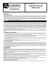
MEASURING THE FACTORY RESISTOR:
1. Locate the data wire found in the three conductor ribbon cable extending from the ignition key cylinder. Typically the data wire is
the outer Yellow wire in this cable. Cut the data wire and strip a portion of the insulation on both sides of the cut wire. Connect
the Red test lead of your Ohm Meter to the key cylinder side of the cut wire.
2. Locate the ground wire found in this same three conductor ribbon cable. Typically the center Black wire is ground. Strip back
some insulation from this wire and connect the Black test lead of your Ohm Meter to this wire.
3. With your meter set to the OHM (Resistance) scale, turn the ignition switch to the start position momentarily then release the key.
Note: To prevent the vehicle from cranking, the gear selector can be moved to D or R during step 3.
Measure and make note of the resistance reading after the key is released.
4. Turn the ignition key to the off position, wait 5 seconds, then turn the ignition key again to the start position and release. Recheck
the resistance measured and confirm it is the same as measured in step 3.
5. If the resistance measured in step 3 and 4 is greater than 9K ohms, cut the "Green Loop" wire on the module.
SETTING UP THE MODULE:
Prior to wiring the module to the vehicle, you can set the resistance to match the vehicles Pass Lock system's resistance. To do this;
connect the Grey and Black wires of the control module to a Ground source. Connect the Green wire of the module to + 12 volts.
Connect the Red test lead of your Ohm Meter to the small gauge Red wire of the control module, and connect the Black test lead of
your Ohm Meter to The Black (ground) wire of the module. Using a small screwdriver, adjust the potentiometer accessed through
the small hole found in the top of the control modules housing. Carefully adjust this potentiometers until your meter reading is the
same as that measured in step 3&4 above.
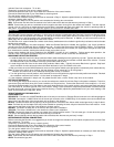
WIRING THE MODULE FOR PASS LOCK II:
2 PIN CONNECTOR:
RED/WHITE: Connect the 14 AWG Red/White wire of the two pin connector to Chassis Ground as shown in the following diagram.
YELLOW: Connect the 14 AWG Yellow wire of the two pin connector to the 18 AWG Grey of the module, then connect both these
wires to the Light Blue wire of the remote start unit as shown in the diagram.
BLACK: Connect the Black wire by splicing it to the ground wire of the three wire ribbon cable located previously in step 2 above.
Note: The black wire of the ribbon cable may not be suitable for operating the three relays on board the Pass Lock module. In this
case connect the Black of the Pass Lock Module to chassis ground.
BROWN: The Brown 18 AWG wire is not used for the Pass Lock II installation.
YELLOW: The Yellow 18 AWG wire is not used for the Pass Lock II installation.
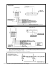
GREEN: Connect this input to the ignition one output of the vehicles ignition switch. This wire must get +12 volts when the ignition
is in the run and start positions and 0 volts when the key is turned off.
BLUE: Connect the Blue wire to the key switch side of the data wire that was cut previously in step 1.
BEFORE MAKING THE FINAL CONNECTIONS:
Before connecting the Red wire, we suggest that you check once again the resistance of the module compared to the vehicles Pass
Lock resistance. To do this:
Temporarily connect the Grey wire to chassis ground.
Connect the Red test lead of your Ohm Meter to the Red wire of the control module.
Connect the Black test lead of your Ohm Meter to chassis ground.
Turn the ignition switch to the "on" position.
Confirm that the resistance reading is the same as measured in Step 3. Adjust the potentiometer as necessary to match the factory
resistance reading taken earlier.
Turn the ignition switch to the off position and complete the following two connections.
RED: Connect the Red wire from the module to the vehicle side of the data wire that was cut previously in Step 1.
GREY: Reconnect the grey wire
2