


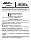

85
30
86
87a
87
To +12 Volt Source
To Light Green Wire
Of AS-9501a
Figure #1
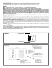
CONFIGURATION: Pulsed Ground Output from Aftermarket Remote Keyless or Alarm System.
THIS INSTALLATION WILL REQUIRE THAT THE DIP SWITCHES BE SET TO 1 OFF, 2 OFF.
WIRING:
Red: +12 volt Battery Source. Connect this wire toa+12volt constant battery source.
Black: Chassis Ground. Connect this wire to a clean solid metal chassis ground source in the vehicle.
Orange: Connect this wire to the pulsed ground output wire from the alarm system that is activated when an unused channel
of the remote alarm is activated. This is normally the low current, ground trigger, 2nd or 3rd channel control wire. When dip
switch #2 is selected to the off position only one trigger control wire is required, and in these cases the orange wire is used.
Green: No connection is required for the green wire when using the AS-9501a as a single wire activated unit. Insulate the
end of this wire with electrical tape.
Blue: No connection is required for the blue wire when using the AS-9501a as a single wire activated unit. Insulate the end
of this wire with electrical tape.
Light Green Wire: This wire will provide a low current ground signal when the alarm or keyless entry transmitter button is
pressed. This wire will be connected to the trigger input of the device you wish to control. This output is capable of 500 mA
maximum current. If the device you are connecting this wire to requires more than 500mA to operate, then a relay will be
required. SEE FIG.# 1 for relay wiring configuration.
The duration of the ground signal on the Light Green trace wire is fully adjustable from a minimum of 0.8 seconds (800ms),
to a maximum of 60 seconds. This adjustment is controlled by the potentiometer located through the side of the module's
case. Turning this adjustment clockwise will increase the output duration. Turning the adjustment counter clockwise will
decrease the output duration.
CAUTION: This unit's potentiometer is capable of a maximum of 180° rotation. DO NOT overturn this adjuster or damage
will occur.
Testing The Installation:
Press the appropriate transmitter button from the alarm system which controls the trigger wire connected to the Light Green
trace wire of the AS-9501a. The AS-9501a will activate the accessory that it is connected to. Some timing adjustments may
be required to make the accessory operate correctly.
Figure #2
Light Green Wire