


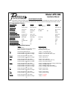

Eighth Press and release the valet switch 1 chirp = siren and horn output
Press transmitter Lock button to change 2 chirps = siren output only
Press transmitter lock button to change 3 chirps = horn output only
or
Ninth Press and release the valet switch 2 chirps = horn chirp output 16mS
Press transmitter Lock button to change 3 chirps = horn chirp output 30mS
Press transmitter Lock button to change 1 chirp = horn chirp output 10 mS
or
Tenth Press and release the valet switch 2 chirps = valet switch override operation
Press transmitter Lock button to change 1 chirp = custom code override operation
or
Eleventh Press and release the valet switch 2 chirps = 2 step unlock off
Press transmitter Lock button to change 1 chirp = 2 step unlock on
or
Twelfth Press and release the valet switch 2 chirps = chirp delete from transmitter inactive
Press transmitter Lock button to change 1 chirp = chirp delete from transmitter active
Press and release the valet switch Exit program mode
or
Turn ignition key off Exit program mode
Note : Once you enter the feature programming mode, do not allow more than 15 seconds to pass between steps or the
programming will be terminated.
The APS-996 Remote Start/Alarm System is designed to be used with Automatic Transmission- Fuel
Injection Vehicles Only! The unit provides a selectable ignition control that allows a number of selectable
timed outputs for glow plug pre-heat in addition to a "Wait To Start Input" either of which may be required for certain
diesel vehicles, (see selectable feature #9 & or Green/Yellow Wire)
. If the diesel engine has a instant fire, (no
glow plug pre-heat system), feature #9 should remain in the default Gasoline mode setting. For diesel
applications, consult your dealer for the type of ignition system used in your particular vehicle. Regardless
of the vehicle, Gasoline or Diesel, for every installation, the vehicle MUST HAVE a Tach Signal Input,
Automatic Transmission and Fuel Injection.
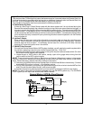
INSTALLATION OF THE MAJOR COMPONENTS:
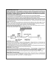
CONTROL MODULE:
Select a mounting location inside the passenger compartment (up behind the dashboard). The mounting
location selected must be within 24" of the ignition switch wiring harness to allow connection of the 6 pin
main wiring harness.
Be certain that the chosen location will not interfere with proper operation of the vehicle. Avoid mounting the
module to or routing the wiring around the steering shaft/column, as the module or wiring may wrap around
or block the steering wheel preventing proper control of the vehicle. Secure the module in the chosen
location using cable ties or screws as necessary.
Do Not Mount The Module In The Engine Compartment, as it is not waterproof.
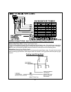
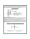
SIREN:
Select a location in the engine compartment that is not accessible from below the vehicle. The selected
location must be clear of hot or moving parts within the engine compartment The siren must be pointed
downward to prevent water retention and the flared end must be pointed away from and out of the engine
compartment for maximum sound distribution. Before securing the siren, check behind your chosen
location to assure that the mounting screws will not penetrate any factory wiring or fluid lines. Secure the
siren mounting bracket using #8 self taping screws or by first using the mounting bracket as a template,
scribe or mark the mounting holes. Drill the marked holes using a 1/8" drill bit, then mount the siren using
#8 sheet metal screws.
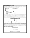
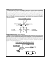
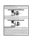
HOOD AND TRUNK PIN SWITCHES:
The pin switches included in this package are intended for protecting the hood and trunk areas of the
vehicle. In all cases, the switch must be mounted to a grounded metal surface. When the pin switch is
activated, (hood/trunk open), it will supply a ground to the input wire activating the alarm. In addition, the
2