


only need to be connected to one door switch, no matter how many doors the vehicle has.
WARNING: Do not use the brown wire if the vehicle has + 12 Volt output type door switches. (see PURPLE
WIRE)
PURPLE WIRE: + DOOR TRIGGER
If the vehicle’s door courtesy light switches have a + 12 volt output when the door is opened ( most Fords and some
Imports ), you must connect this wire to the positive output from one of the door switches. In most cases, the purple
wire will only need to be connected to one door switch, no matter how many doors the vehicle has.
WARNING: Do not use the purple wire if the vehicle has ground output type door switches. (see BROWN WIRE)
ORANGE WIRE: GROUND OUTPUT WHEN ARMED
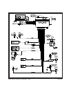
This wire is provided to control the optional (not included) starter cut relay. Connect the orange wire to terminal 86
of the AS-9256 relay (or equivalent 30A automotive relay), and wire the remaining relay contacts as shown in the
wiring diagram.
IMPORTANT: Audiovox does not recommend using this relay to interrupt the ignition wire. Only connect
this relay to the low current starter solenoid feed wire, as indicated on the wiring diagram
of the AS-9256.
VALET SWITCH: 2 Pin Blue Connector
Route the grey and black wires in the 2 pin connector from the valet switch to the control module, and
plug it into the mating blue connector on the side of the module.
DASH MOUNTED LED: 2 Pin White Connector
Route the red and blue wires in the 2 pin white connector from the LED to the control module, and plug
it into the mating white connector on the side of the module.
RED & GREEN 2 PIN CONNECTOR: DOOR LOCK OUTPUTS
These wires will provide either a pulsed ground output to the factory door lock control relay, or a pulsed
+ 12 volt output to the factory door lock control relay. In either case, the maximum current draw through
these outputs must not exceed 300 mA.
3 Wire Ground Switched Door Locks
In this application, the red wire provides a ground pulse during arming (pulsed ground lock) output.
Connect the red wire to the wire that provides a low current ground signal from the factory door lock
switch to the factory door lock control relay.
The green wire provides a ground pulse during disarming (pulsed ground unlock) output. Connect the
green wire to the wire that provides a low current ground signal from the factory door unlock switch to the
factory door lock control relay.
3 Wire Positive Switched Door Locks
In this application, the red wire provides a positive pulse during disarming (pulsed + 12 volt unlock)
output. Connect the red wire to the wire that provides a low current positive signal from the factory door
unlock switch to the factory door lock control relay.
The green wire provides a positive pulse during arming (pulsed + 12 volt lock) output. Connect the
green wire to the wire that provides a low current positive signal from the factory door lock switch to the
factory door lock control relay.
Resistive Circuits, As Well As 4 Wire Polarity Reversal and 5 Wire Alternating 12 Volt Door Lock Control
Circuits
These applications require the use of additional components which may include relays, fixed resistors, or for
convenience, the AS 9159 Door Lock Interface. Refer to the AUDIOVOX Door Lock Wiring Supplement and or the
Audiovox fax back service for information on your particular vehicle for properly connecting to these types of
circuits.
Page 4