


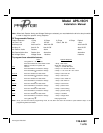
128-6462
4 of 6
DARK GREEN WIRE: (-) INSTANT TRIGGER
This is an instant on ground trigger wire. It must be connected to the previously installed hood and trunk pin
switches.
BROWN WIRE: - DOOR TRIGGER
If the vehicle’s door courtesy light switches have a - ground output when the door is opened ( GM and most
Imports ) you must connect this wire to the negative output from one of the door switches. In most cases, the
brown wire will only need to be connected to one door switch, no matter how many doors the vehicle has.
WARNING: Do not use the brown wire if the vehicle has + 12 Volt output type door switches.
(see PURPLE WIRE)
Note for vehicles with interior delay lighting see programming under title "Completing The Installation".
PURPLE WIRE: + DOOR TRIGGER
If the vehicle’s door courtesy light switches have a + 12 volt output when the door is opened ( most Fords and
some Imports), you must connect this wire to the positive output from one of the door switches. In most cases,
the purple wire will only need to be connected to one door switch, no matter how many doors the vehicle has.
WARNING: Do not use the purple wire if the vehicle has ground output type door switches.
(see BROWN WIRE)
Note for vehicles with interior delay lighting see programming under title "Completing The Installation".
ORANGE WIRE: GROUND OUTPUT WHEN ARMED
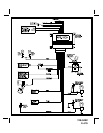
This wire is provided to control the OPTIONAL starter cut relay. Connect the orange wire to terminal 86 of the
relay and wire the remaining relay contacts as shown in the wiring diagram.
IMPORTANT: Audiovox does not recommend using this relay to interrupt the ignition wire. Only
connect this relay to the low current starter solenoid feed wire, as indicated on the wiring
diagram.
GREY & BLACK 2 PIN (blue) CONNECTOR: VALET SWITCH
If you have not done so already, route the two conductor, blue connector from the previously installed valet switch
to the alarm control module and plug it into the mating blue connector on the end of the module.
RED & BLUE WIRES: DASH MOUNTED LED
Route the two conductor, white connector (red and blue wires) from the previously installed LED to the alarm
control module and plug it into the mating white connector on the end of the module.
RED & GREEN 2 PIN (white) CONNECTOR: DOOR LOCK OUTPUTS
These wires will provide a pulsed ground output to the factory door lock control relay. The maximum current
draw through these outputs must not exceed 300 mA.
3 Wire Ground Switched Door Locks
In this application, the red wire provides a ground pulse during arming (pulsed ground lock) output. Con-
nect the red wire to the wire that provides a low current ground signal from the factory door lock switch to the
factory door lock control relay.
The green wire provides a ground pulse during disarming (pulsed ground unlock) output. Connect the
green wire to the wire that provides a low current ground signal from the factory door unlock switch to the
factory door lock control relay.
Page 4