


128-6711
4 of 8
4
GREEN/BLACK Wire: Immediate, 300mA Duration of Transmit, Channel 3 Output
The Green/Black wire supplies a 300mA switched output whenever Channel 3 of the receiver is accessed. Pressing A
combination of the transmitter Lock/UnLock buttons simultaneously will access Channel 3 and will remain active for as
long as the transmitter button(s) is held. This is a low current output and must be connected to a relay to supply power to
the device you intend to control. Connect Green/Black Trace wire to terminal #86 of a VF45F11 P&B relay or equivalent.
Connect terminal #85 of the relay to a fused + 12 volt source. Connect the common, normally open, and normally closed
contacts of the relay to perform the selected function of the Channel 3 output.
ORANGE Wire: Ground When Armed Output
This wire provides a 300mA ground output when the keyless entry is locked to control the optional starter inhibit relay.
Connect the Orange wire to terminal #86 of a standard SPDT relay. Connect terminal #85 of the relay to an ignition wire
in the vehicle that is +12VDC when the ignition key is turned to the on and start positions and off when the key is in the off
position. Locate and cut the low current starter solenoid wire found at the vehicle's ignition switch harness. This wire will
have +12VDC when the ignition key is moved to the start (crank) position and will have 0 volts in all other key positions.
Connect one side of the cut wire to terminal #87a of the relay. Connect the other side of the cut wire to terminal #30 of the
relay.
DOOR LOCK/UNLOCK CONTROL HARNESS (3PIN White Plug w/3 Wires; RED, GREEN, & RED/BLACK)
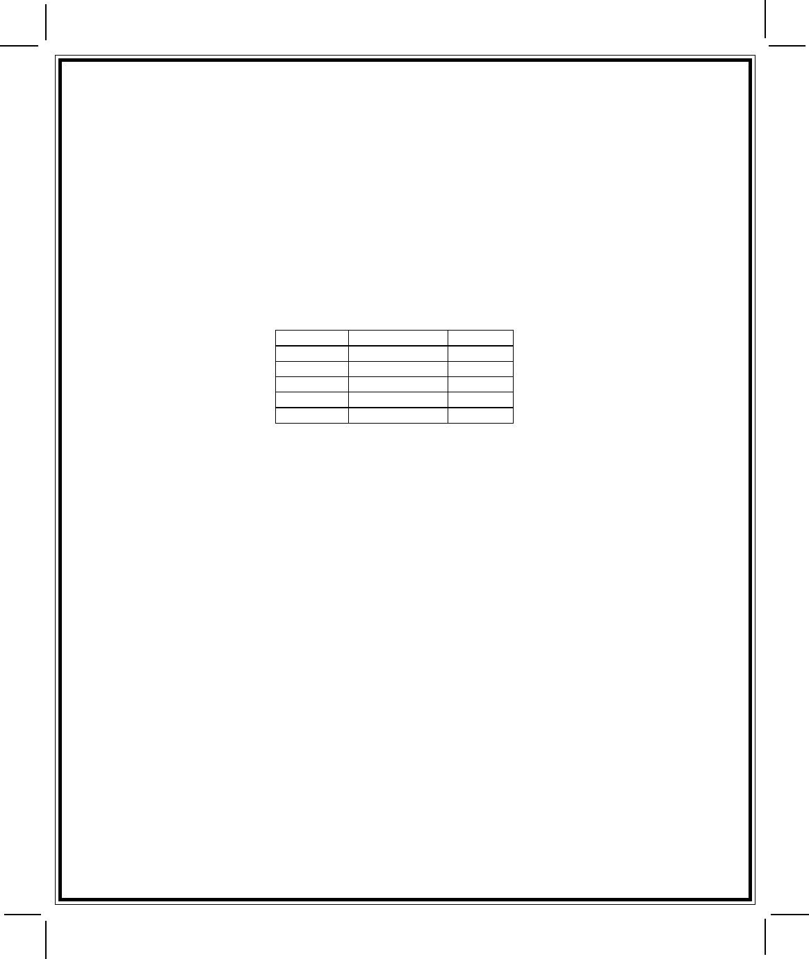
The Red and Green Door Lock/Unlock output wires provide either a momentary pulsed ground (-) or a momentary pulsed
+12VDC (+) output for controlling a vehicle's power door lock/unlock circuit. To better understand this, refer to the table
below:
The Red w/Black trace wire will provide a pulsed ground only and will only provide an output when the lock/unlock button
of the transmitter is pressed a second time after a first unlock command was issued. This is used for second step unlock
or all doors unlock in a two step circuit. In this arrangement, Red is used to control the drivers door unlock relay and the
Red/Black will be used to control unlock of all other doors.
3 Wire Ground Switched Signal Step Door Locks
In this application, the red wire provides a ground pulse during arming, or the pulsed ground lock output. Connect the red
wire to the wire that provides a low current ground signal from the factory door lock switch to the factory door lock control relay.
The green wire provides a ground pulse during disarming, or the pulsed ground unlock output. Connect the green wire to the
wire that provides a low current ground signal from the factory door unlock switch to the factory door lock control relay. Red/
Black Not Used.
3 Wire Ground Switched 2 Step Door Locks
In this application, the red wire provides a ground pulse during locking, or the pulsed ground lock output. Connect the red
wire to the wire that provides a low current ground signal from the factory door lock switch to the factory door lock control relay.
The green wire provides the first ground pulse during unlocking, or the drivers door pulsed ground unlock output.
Connect this wire to the drivers door unlock relay that requires a low current ground signal to unlock only the driver's door.
If the vehicle does not have a separate driver's door relay, one will have to be added. Locate the driver's door unlock motor
wire and cut it at a convenient location to allow wiring of an optional relay. Connect the door side of the cut wire to terminal
30 of the optional relay added. Connect the vehicle side of the cut wire to terminal 87a of the optional relay added. Connect
the green wire of the 3 pin harness to terminal 86 of the optional relay added. Connect terminal 85 of the optional relay
added to a fused constant + 12 volt source. Most vehicles door lock/unlock motor legs rest at ground and switch +12 volts
to the door lock/unlock motor legs for operation. If this is the case in the vehicle you are working on, connect the remaining
terminal 87 to a fused + 12 volt source. In the rare instance that the vehicle door lock/unlock motor legs rest at + 12 volts
and switches ground to the door lock/unlock motors, connect the remaining terminal 87 to chassis ground.
The Red/Black wire provides a pulse ground output when the unlock button of the transmitter is pressed a second time
after unlocking the driver's door. Connect the Green/Black wire to the wire that provides a low current ground signal from
the factory door unlock switch to the factory door lock control relay.
3 Wire Positive Switched Door Locks
In this application, the red wire provides a positive pulse during unlocking, or the pulsed + 12 volt unlock output. Connect
the red wire to the wire that provides a low current positive signal from the factory door unlock switch to the factory door lock
control relay.
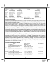
Wire Color Function Polarity
Red Lock Ground (-)
Red Unlock Positive (+)
Green Lock Positive (+)
Green Unlock Ground (-)
Green/White 2nd Unlock Pulse Ground (-)
Red/Black