


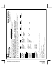

128-8129
6 of 28
6
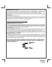
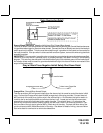
DASH MOUNTED LED:
The small LED included in the kit will serve as a visual indicator of the alarm's status and provide a visual
deterrent to a potential thief. The LED also provides important feed back information during the transmitter
and feature program modes. The LED should be installed in the dash in an area highly visible so that it may
be seen from the driver's seat as well as from outside the vehicle. Inspect behind the chosen location to
insure that the drill will not penetrate any existing factory wiring or fluid lines. Carefully drill a 1/4" hole in
the desired location and pass the connector end of the LED through the hole and toward the control
module. Press the LED firmly into place until it is fully seated in the mounting hole.
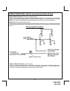
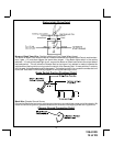
THE RECEIVER/ANTENNA ASSEMBLY:
The Superheterodyne Receiver Antenna Assembly provided with this unit allows routing from below the
dash board for maximum operating range. Choose a location above the belt line (dashboard) of the vehicle
for best reception. Special considerations must be made for windshield glass as some newer vehicles
utilize a metallic shielded window glass that will inhibit or restrict RF reception. In these vehicles, route
the antenna toward a rear window location for best reception. Secure the antenna with double stick tape
provided. After securing the antenna with tape, we advise also securing a section of the antenna cable to
a fixed support. This will prevent the antenna from dropping down in case the double stick tape is exposed
to extreme heat which may loosen it's gummed surface. Route the connector toward the control module
using caution not to pinch the cable as this will cause poor or no RF reception to the control module.
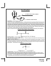
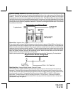
PUSHBUTTON LED SWITCH
Select a mounting location known and accessible to the operator of the vehicle. A dash knockout plug or
front dash panel is desirable as the now Push-Button LED assembly needs the LED to be visible from the
outside of the vehicle and will be used for valet modes, programming features, programming transmitters,
and for overriding the remote start unit when the vehicle is being serviced. Inspect behind the chosen
location to insure that adequate clearance is allowed for the body of the switch, and also that the drill will
not penetrate any existing factory wiring or fluid lines. Drill a 5/16" or 8mm hole in the desired location and
mount the switch by passing the connectors, one at a time, through the panel from the front side and
pressing on the bezel until the switch is fully seated.
CONTROL SWITCH:
Select a mounting location known and accessible to the operator of the vehicle. A lower dash panel, kick
panel, or glove box is desirable. Inspect behind the chosen location to insure that adequate clearance is
allowed for the body of the switch, and also that the drill will not penetrate any existing factory wiring or fluid
lines. Drill a 1/4" hole in the desired location and mount the switch by passing it through the panel from the
underside. Secure the switch using the nut, star washer, and on/off face plate. It is suggested that the
switch be oriented to allow the on position to be up toward the driver and the off position to be down or away
from the driver. Route the switch's connector toward the control module.
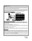
SHOCK SENSOR:
Select a centrally located, solid mounting surface for the shock sensor that will allow consistent operation
from all areas of the vehicle. The selected location must be within 18" of the control module to allow
routing and connecting of the 4 pin harness. Secure the shock sensor to the chosen location using two #8
self tapping sheet metal screws. The sensor can also be secured to an existing dash brace using cable
tie straps. Whichever mounting method is used be sure to allow access to the sensitivity adjustment
potentiometer for use later in the installation.
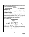
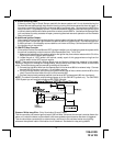
STARTER INHIBIT RELAY:
Select a mounting location within 12" of the ignition switch's low current start solenoid wire. Secure the
relay to an existing harness in the chosen location using a cable tie around the relay's wiring harness.
CAUTION! Do not wire tie the metal bracket to an existing wiring harness as vibration may cause chaffing
and shorting damaging the factory wiring. If an existing harness is not available then secure the relay's
metal mounting tab to an under dash metal brace with a #8 self tapping sheet metal screw. Wire the relay
as per the diagram found later in this manual.
This unit is to be used in vehicles with AUTOMATIC TRANSMISSIONS only! Although this combination
Alarm/Remote Start unit is a sophisticated system with many advanced features, IT MUST NOT be
installed into a vehicle with a manually operated transmission. Doing so may result in serious personal