


MCS-100
3
Version A
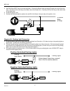
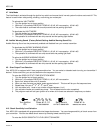
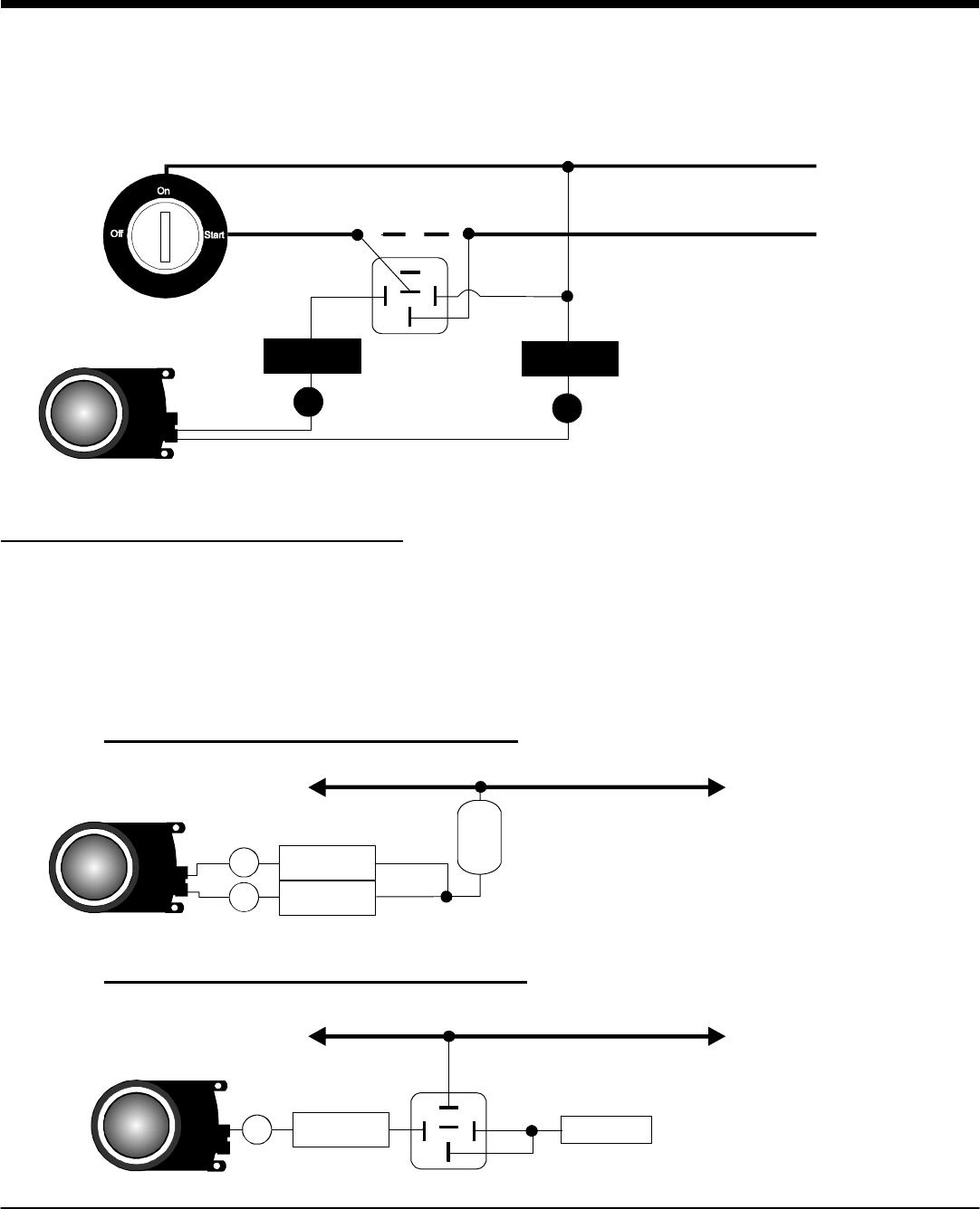
2. Use 30/40 Amp SPDT relay to connect as shown. Connect the Starter Interrupt output (Orange) wire to pin 86 of the
relay. Connect pin 30 of the relay to the Motor side of the Starter wire. Connect pin 87a of the relay to the switch side
of the Starter wire.
3. Locate the Ignition wire.
4. Connect the Switched ignition (yellow) wire and 85 of the Starter Interrupt relay to the Ignition wire.
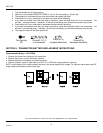
Diagram #4: Parking Light Connection
1. Locate the parking light wire or signal wire that switches from Ground to +12V when turning on the parking lights or
signal lights. (usually near the parking light switch)
2. Connect the parking light output wire (White) to the parking light wire of the motorcycle. We have two parking light
output wires for two separate (left & right) controls for the parking lights. (If there is only one control for the parking
lights, then connect both white wires to the same parking light.)
3. If the parking light wire switches from +12V to Ground when turning on parking lights, use a 20/30A SPDT relay to
invert the control signal polarity.
87
86
85
87a
30
To Starter
Motor
or Relay
x
Cut
Orange
1
Yellow
3
Parking
Light Switch
Parking Lights
2
0
A
F
u
s
e
If alarm doesn't have fuse, connect
fuse in line for security reasons.
Positive Controlled Parking Lights
White
White
6
8
Parking
Light Switch
Parking Lights
87
86
85
87a
30
Ground
Negative Controlled Parking Lights
White
8