


10
PLACING THE RS4000 PEDESTAL UNIT
Remove the cover from the RS4000 operator by removing the four
1/4-20 diameter bolts that secure it to the chassis. Set the cover aside
for the time being.
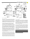
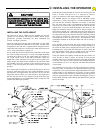
The recommended procedure for securing the RS4000 pedestal to
concrete, or fresh concrete pad (for those installations where the
anchor bolts were not previously installed) is to locate and drill the
hole for the mounting bolt nearest to the gate post first. Locate this
hole by referring to the diagram in Figure 6 for the basic dimensions
and gate/operator relationship. After placing a bolt in this pedestal
mounting hole, mark and drill the remaining three mounting holes.
This can be accomplished with the operator in place.
Before inserting the remaining three bolts, check the pedestal to
ensure that it is plumb and level. Flat washers may be used to shim
and elevate a low corner. Snug down all four bolts with nuts and lock
washers when complete.
For previously placed anchor bolts, the procedure is the same except
that the bolts will already be in place. If 1/2" diameter anchor bolts
were set, the 3/4" mounting holes on the RS4000 pedestal will allow
some adjustment for desired alignment. Washers can be used under
low corners to accurately level the unit as above.
TO REVIEW: Make sure the correct position of the pedestal or post
from the center line of the gate hinge pivot point to the center line of
the RS4000 output shaft is in accordance with the drawing in
Figurez6.
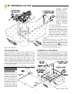
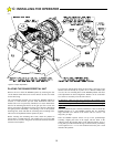
After the pedestal or post is securely installed, it is time to mount the
RS4000 operator to it. The RS4000 operator has two mounting
angles fastened to the bottom of the chassis with two 3/8-16 x 3/4
long bolts, per angle.
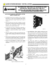
Place the RS4000 operator chassis on top of the pedestal/angle
assembly, aligning the holes in the angles with the holes in the
pedestal. Secure the operator angles to the pedestal with the 3/8-16 x
5 long bolts provided in hardware bag. See Section B for preliminary
work required if a 4 x 4 x 1/8 wall structural steel tube post is used
instead of the pedestal.
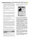
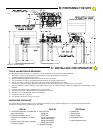
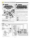
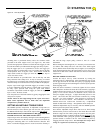
Figure 9: Torque Adjustment
106513
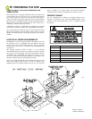
C: INSTALLING THE OPERATOR