Electrical Rating:
Voltage: 24 Volts, (30 Volts Max.), 60 Hz.
Current Rating: 0.23 Amps
Type of Gas
Natural Gas
Pressure Rating:
1
⁄2 lb. per sq. in. (14” W.C.)
Pressure Regulator Setting:
Adjustable from 2.5 to 5.0" W.C.
(Factory preset for 3.5" W.C.)
Ambient Temperature: -40° to 175°F
Thermocouple:
30 millivolt type
PIPE SIZES/CAPACITIES
Pipe Size
(inches)
Capacity (BTU/hr) at
1” pressure drop across valve
1
⁄
2
” x
3
⁄
8
”
1
⁄
2
” x
1
⁄
2
”
1
⁄
2
” x
3
⁄
4
”
3
⁄
4
” x
3
⁄
4
”
100,000
230,000
230,000
280,000
162,000
372,600
372,600
453,600
Nat. Gas
(1000 BTU/cu. ft.,
64 Sp. Gr.)
LP Gas
(2500 BTU/cu. ft.,
1.53 Sp. Gr.)
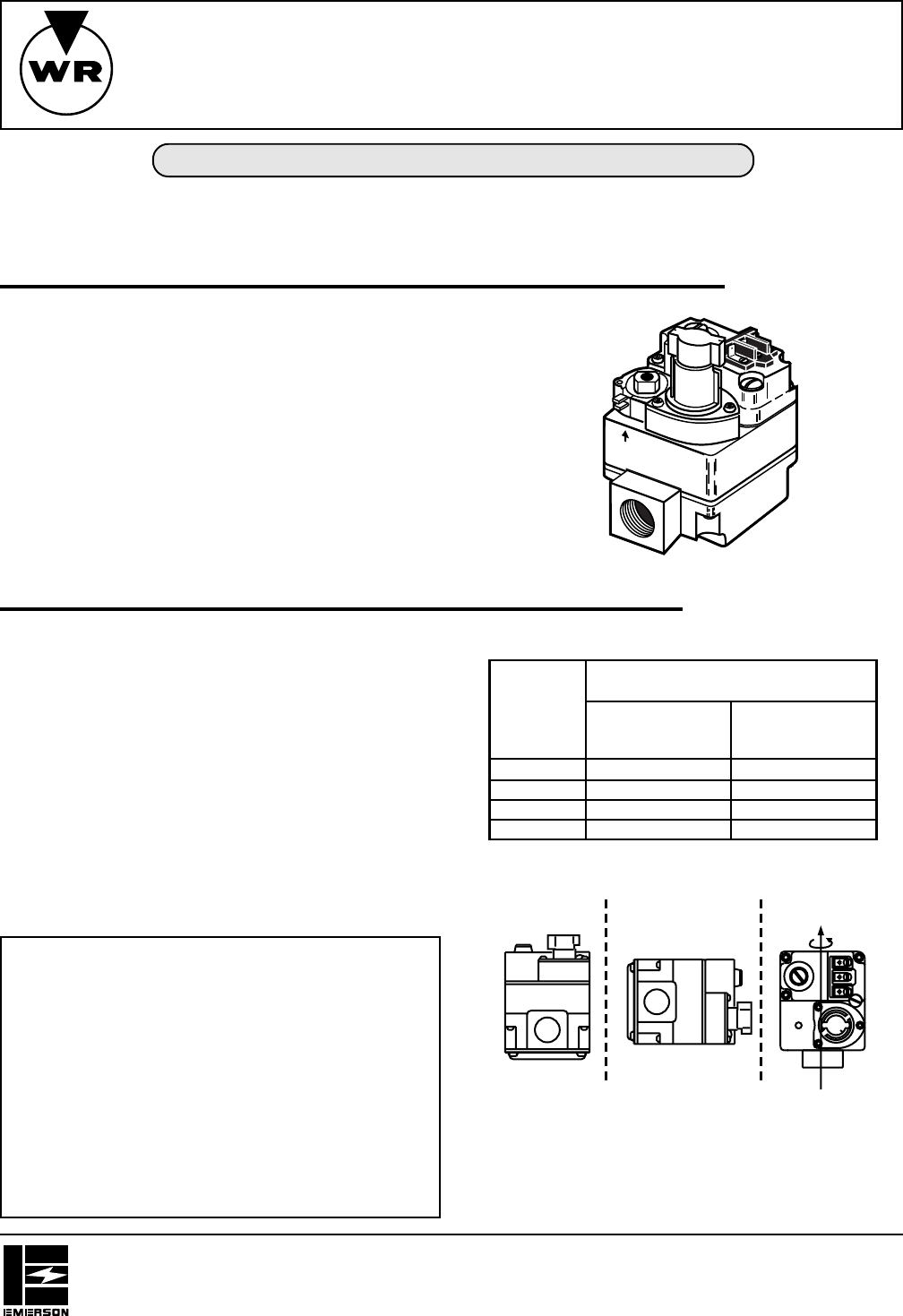
INLET BOSS
UP OR DOWN
UPRIGHT
LEFT OR RIGHT
Upright, 90° from upright or vertical
NOTE: Control shown may not be identical
to replacement control.
ON
OFF
Figure 1. Gas valve mounting positions
WHITE-RODGERS DIVISION
EMERSON ELECTRIC CO.
9797 REAVIS ROAD, ST. LOUIS, MO 63123-5398
(314) 577-1300, FAX (314) 577-1517
9999 HWY. 48, Markham, ONT, L3P 3J3
(905) 475-4653, FAX (905) 475-4625
Printed in U.S.A.
PART NO. 37-5825B
Replaces 37-5825A
0024
INSTALLATION INSTRUCTIONS
WHITE-RODGERS
FAILURE TO READ AND FOLLOW ALL INSTRUCTIONS CAREFULLY BEFORE
INSTALLING OR OPERATING THIS CONTROL COULD CAUSE PERSONAL INJURY
AND/OR PROPERTY DAMAGE.
The multi-function gas controls combine into a single
package the functions of 3-position gas cock, main gas
valve, pressure regulator and 100% shut-off automatic
pilot. The pilot gas outlet accepts a
1
⁄4” pilot line connec-
tion.
This model features a slow opening main valve that
provides a softer ignition and E.C.O. connections.
To permit replacement of a variety of valve sizes, some
models are furnished with two reducer bushings (two
3
⁄4”
to
1
⁄2”). Also included is an E.C.O. jumper wire that allows
this valve to be used on an installation without electrical
cut off device.
Operator: Save these instructions for future use!
DESCRIPTION
SPECIFICATIONS
36C53
Combination Gas Valves
(24 Volt Model)
CONTENTS
Description ......................................................... 1
Specifications ..................................................... 1
Precautions ........................................................ 2
Installation.......................................................... 2
Main Piping Connection
Pilot Gas Connection
Energy Cut Off (E.C.O.) Connection
Thermocouple Connection
System Wiring
Adjustment ......................................................... 4
Pilot Gas Adjustment
Pressure Regulator Adjustment
Pilot Lighting Instructions and Precautions ........ 5
OFF
PILOT
ON
E.C.O


