


4
©
2006
Directed Electronics, Inc.
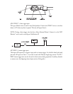
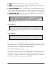
H1/8 GREEN (-) door trigger input
Most vehicles use negative door trigger circuits. Connect the GREEN wire to a wire showing
ground when any door is opened. When connecting to newer model vehicles there is generally a
need to use individual door triggers. See DirectFax document 1076 for wiring instructions. This
wire will report Zone 3.
NOTE: If using a door trigger wire that has a delay, Advanced Menu 2, feature 6, or the 998T
Bitwriter
®
can be used to turn Bypass Notification off.
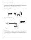
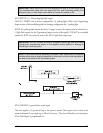
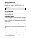
H1/9 BLACK/WHITE high current output from on-board domelight supervision relay
Connect this wire directly to the domelight circuit in the vehicle. The on-board relay will drive
circuits up to 20 amperes. The polarity of this output is determined by the connection of the input
wire H2/A in the Relay Harness.
NOTE: If the input wire H2/A is not connected, there will be no output on this wire.
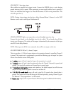
H1/10 WHITE/BLUE 200 mA (-) channel 3 output
This wire provides a (-) 200 mA output whenever the transmitter button(s) controlling Channel 3
is pressed. This output can be programmed to provide the following types of output (see System
Features Learn Routine section of this guide):
➤➤
A
vvaalliiddiittyy
output will send a signal as long as the transmission is received.
➤➤
A
llaattcchheedd
output will send a signal continuously when the Channel 3 button(s) is pressed and
released. The signal will continue until channel three is pressed again.
➤➤
A
llaattcchheedd//rreesseett wwiitthh iiggnniittiioonn
output works similar to the latched output, but will also reset
(output will stop) when the ignition is turned on and then off.
➤➤
A
3300 ((6600,, 9900)) sseeccoonndd ttiimmeedd
output will send a signal for 30 seconds when channel three is
pressed. This output can be shut off during the 30-second period by pressing Channel 3 again.
The Bitwriter
TM
can program from 1 to 180 seconds.
➤➤
RReemmoottee ssttaarrtt
output (refer to System Features Menu description for additional information).