


6
©
2006
Directed Electronics, Inc.
Auxiliary Harness Wire Connection Guide
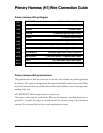
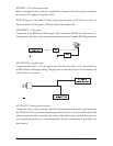
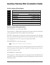
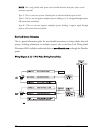
Auxiliary Harness Wiring Diagram
___
___
___
___
___
___
___
___
Auxiliary Harness Wiring Instructions
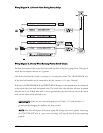
H2/1 LIGHT BLUE (-) second unlock output (200mA)
This wire produces a (-) 200mA output for progressive locks in which the driver door unlocks first
and the remaining locks unlock with a second press of the unlock button.
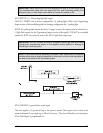
H2/2 GREY (-) hood pin input, zone 6 This wire is connected to hood pinswitch. This will trigger
the security system if the hood is opened while the system is armed and report Zone 6. This input
can be programmed for N.O. or N.C. contact, refer to Systems Features Menus.
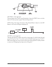
H2/3 ORANGE/BLACK (-) retained accessory output
NNOOTTEE
: An additional relay (not supplied) is required for most applications.
Connect this wire to the accessory wire in the vehicle that powers the accessories in the vehicle. This
wire will retain power after the ignition key is turned off. This output ceases when a door is
open/closed or the system is armed.
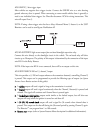
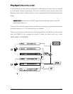
H2/4 GRAY/BLACK (-) channel 6 output
This wire provides a (-) 200mA output whenever the transmitter button(s) controlling Channel 6
is pressed. This output can be programmed to provide the following types of outputs (see also the
Feature Menus section):
LIGHT GREEN/BLACK (-) Factory Disarm Output
LIGHT BROWN (-) Horn Honk Output
VIOLET/BLACK (-) Channel 4 Output
WHITE/BLACK (-) Channel 5 Output
GREY/BLACK (-) Channel 6 Output
ORANGE/BLACK Retained Accessory Output
GREY (-) Hood Pin Input, Zone 6
LIGHT BLUE (-) Second Unlock
H2/1
H2/2
H2/3
H2/4
H2/5
H2/6
H2/7
H2/8