


©
2006
Directed Electronics
1
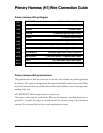
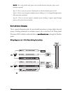
Primary Harness (H1) Wire Connection Guide
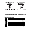
Primary Harness Wiring Diagram
___
___
___
___
___
___
___
___
___
___
___
___
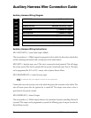
Primary Harness Wiring Instructions
This guide describes in detail the connection of each wire. Also included are possible applications
of each wire. This system was designed with the ultimate in flexibility and security in mind. Many
of the wires have more than one possible function. Please read carefully to ensure a thorough under-
standing of this unit.
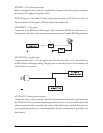
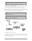
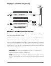
H1/1 RED/WHITE 200 mA output channel 2 (trunk release)
This output is often used for trunk release. Whenever the button(s) controlling channel two is
pressed for 1.5 seconds, this output is activated and will stay activated as long as the transmission
continues. Use an external relay to drive circuits requiring more current.
ORANGE (-) 500 mA Ground-When-Armed Output
WHITE (+)/(-) Selectable Light Flash Output
WHITE/BLUE (-) 200 mA Channel 3 Programmable Output
BLACK/WHITE Domelight Supervision Relay Output #30
GREEN (-) Door Trigger Input, Zone 3
BLUE (-) Instant Trigger Input (trunk input/shunt), Zone 1
VIOLET (+) Door Trigger Input, Zone 3
BLACK (-) Chassis Ground Input
YELLOW (+) Switched Ignition Input, Zone 5
BROWN (+) Siren Output
RED (+) Constant 12V Power Input (15A fused)
RED/WHITE (-) 200 mA Channel 2 Output
H1/1
H1/2
H1/3
H1/4
H1/5
H1/6
H1/7
H1/8
H1/9
H1/10
H1/11
H1/12