


©
2006
Directed Electronics
17
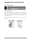
Immobilizer Wire Connection Guide
Immobilizer Wiring Diagram
___
___
___
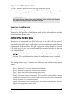
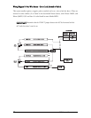
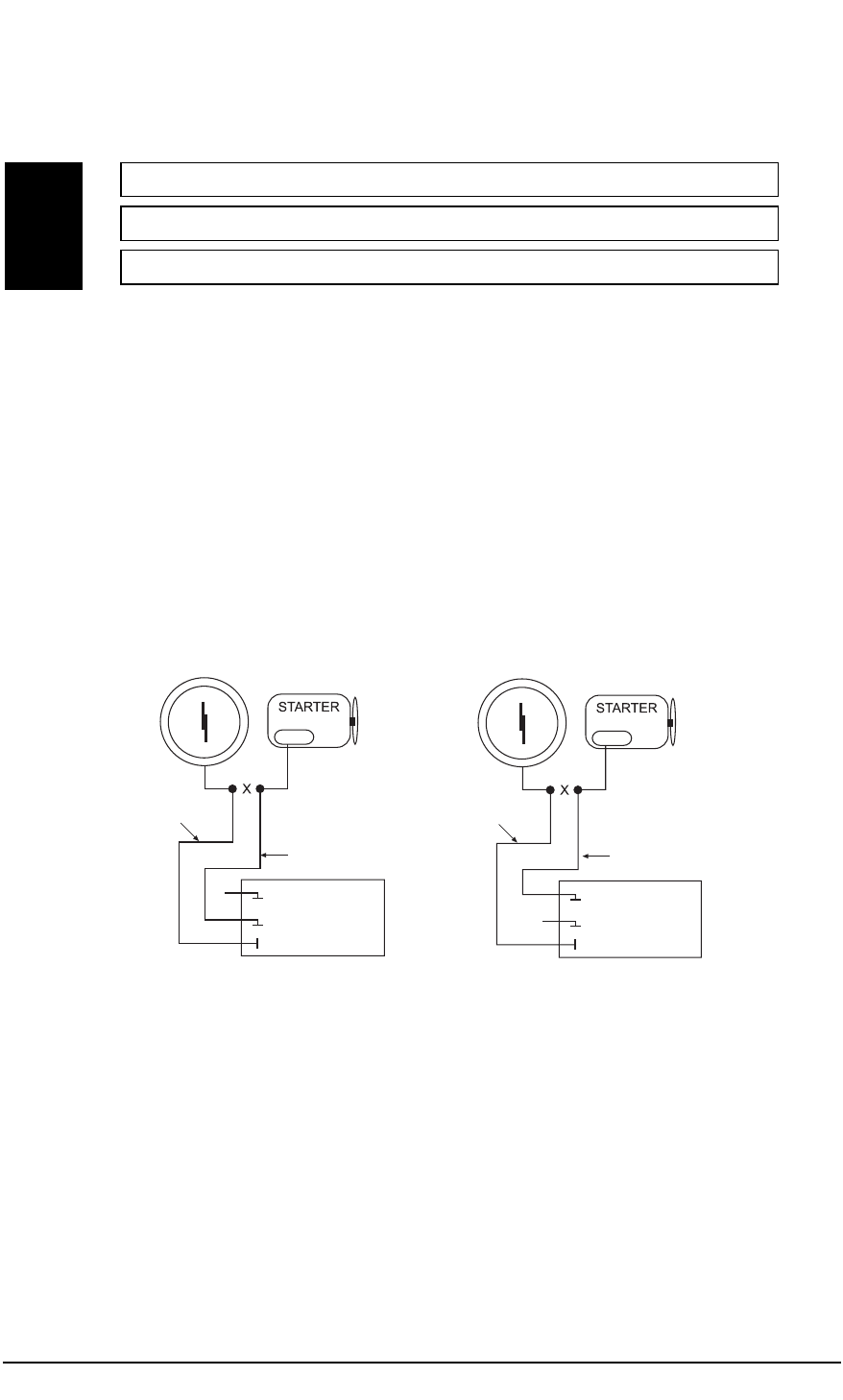
Immobilizer Wiring Guide
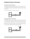
The starter immobilizer harness can be installed as a normally open or normally closed circuit by
connecting the desired side of the three-wire immobilizer. Locate the starter wire, then cut it and
make connections as described in the following diagram. Connect wire C to the end of the wire that
is still connected to the ignition switch; connect A or B wire to the end of the wire that continues
to the vehicle’s starter circuit.
Note: Factory default setting is normally closed, if wired for normally open you must change the
programming.
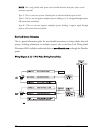
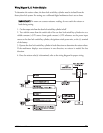
ON BOARD
IMMOBILIZER
NORMALLY OPEN (87)
NOT USED (87A)
COMMON (30)
NORMALLY
OPEN
GREEN/WHITE
GREEN
NORMALLY
CLOSED
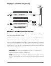
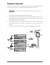
ON BOARD
IMMOBILIZER
NOT USED (87)
NORMALLY CLOSED (87A)
COMMON (30)
GREEN/BLACK
GREEN/WHITE
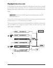
GREEN/WHITE Starter - Common (key side)
GREEN Starter - Normally Open (motor side)
GREEN/BLACK Starter - Normally Closed (motor side)
A
B
C