


16
©
2006
Directed Electronics, Inc.
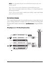
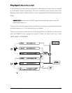
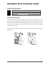
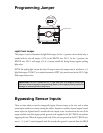
WWiirriinngg DDiiaaggrraamm HH,, ((--)) NNeeggaattiivvee MMuullttiipplleexx
To determine the resistor values, the door lock switch/key cylinder must be isolated from the factory
door lock system. For testing, use a calibrated digital multimeter that is set to ohms.
IIMMPPOORRTTAANNTT!!
To ensure an accurate resistance reading, do not touch the resistor or leads
during testing.
1. Cut the output wire from the door lock switch/key cylinder in half.
2. Test with the meter from the switch side of the cut door lock switch/key cylinder wire to a
reliable ground source. Some good ground references are the ground input source to the door
lock switch/key cylinder or battery ground.
3. Operate the door lock switch/key cylinder in both directions to determine the resistor values.
If the multimeter displays zero resistance in one direction, no resistor is needed for that
direction.
4. Once the resistor value(s) is determined, refer to the wiring diagram for proper wiring.