


©
2006
Directed Electronics
11
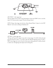
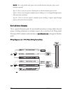
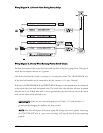
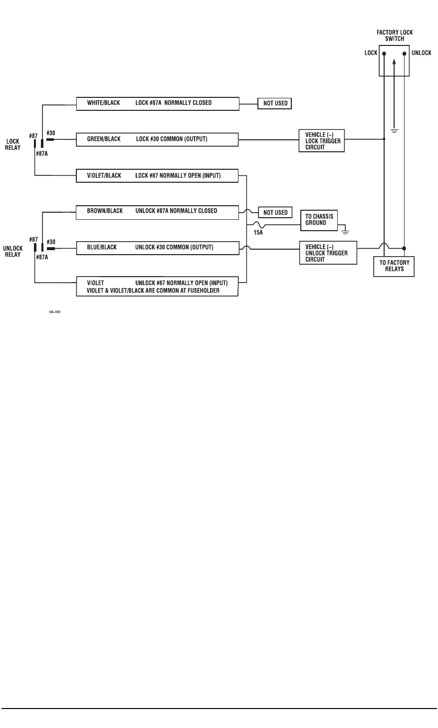
WWiirriinngg DDiiaaggrraamm BB,, ((--)) GGrroouunndd PPuullsseess DDrriivviinngg FFaaccttoorryy RReellaayyss
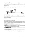
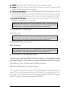
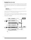
WWiirriinngg DDiiaaggrraamm CC,, DDiirreeccttllyy--WWiirreedd RReevveerrssiin
ngg--PPoollaarriittyy SSwwiittcchh CCiirrccuuiittss
Use these instructions if the power door lock switch has four or five heavy-gauge wires. This type of
switch has two outputs that rest at (-) ground.
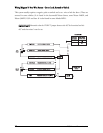
One of the wires from the switch is a constant (+) 12 volt power source. The VIOLET/BLACK wire
of the door lock module can be connected to this for constant (+) 12 volt, if desired.
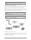
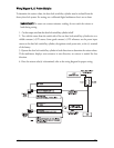
In all cases, the BROWN/BLACK and WHITE/BLACK inputs to the module must be connected
to the switch side of the lock and unlock wires. The switch side is the side that still rests at ground
after the wire is cut. If both sides seem to rest at ground after you have only cut one of the switch
leads, cut the other switch lead and re-rest.
IIMMPPOORRTTAANNTT!!
If these are not connected properly you will send (+) 12 volts directly to (-)
ground, possibly damaging the module or the factory switch.
NNOOTTEE::
Most direct-wired power lock systems require 20-30 amps of current to operate. Connecting
the VIOLET/BLACK wire to a poor source of voltage will keep the door locks from operating
properly.