


Page 8 - G 40RS
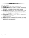
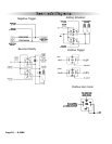
8-Pin Main Harness
Pin 1 RED WIRE: Module Power Input (+). Connect to a constant source of +12V
Pin 2 GREEN/WHITE WIRE: Brake Input (+). Connect to the wire that shows +12V when pressing the
brake. The Green/white wire is a safety shutdown wire that must be connected.
Pin 3 BROWN/WHITE: Horn Output (-) 500 mA. Connect to a relay to activate the vehicle’s horn when the
alarm is triggered. This wire may instead be programmed as an ignition 3 relay trigger
Pin 4 WHITE WIRE: Parking Light Output (+/-) relay. Connect the White wire to the circuit that shows
+12V or ground only when the parking lights are on and set the internal parking light relay jumper to
the proper polarity. For parking light circuits exceeding 10 amps, a relay is required. For vehicle’s with
independent left and right parking light circuits, diodes must be installed to keep the circuits separate.
NOTE: Do not connect the WHITE wire to the vehicle’s headlight circuit.
Pin 5 WHITE/BLACK WIRE: Hood Pin Input (-). Connect the to the hood pin switch. The switch must
provide a ground output when switch is opened.
Pin 6 BLUE/ORANGE WIRE: Ground When Running Output (-) 500 mA. Connect to an optional factory
security bypass module if required.
Pin 7 BLACK WIRE: Ground Input (-). The Black wire must connect to a solid chassis ground. Clean away
any paint or dirt to insure the best possible ground.
Pin 8 BLACK/GRAY WIRE: Tach Input. Connect to the vehicle’s tach wire or a fuel injector wire if the
tachless mode does not provide satisfactory operation.
System
Installation