


© ScyTek Electronics 2009 G 40RS 7-29-09
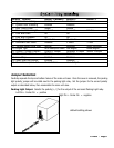
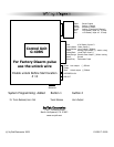
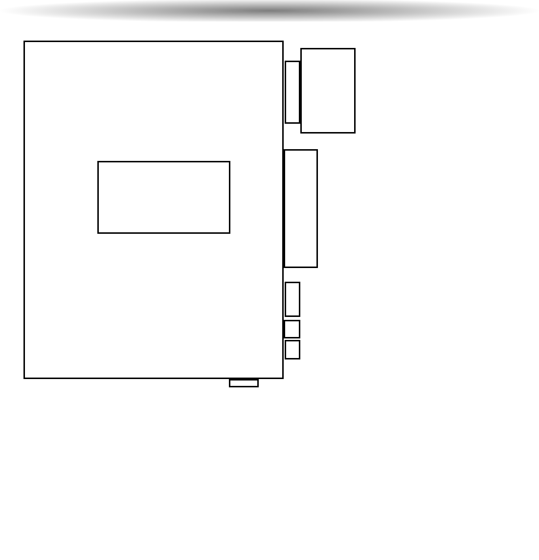
Wiring
Diagram
For Factory Disarm pulse
use the unlock wire
Enable unlock Before Start location
# 12
ScyTek
Electronics
11627 Cantara Street
North Hollywood, CA 91605
www.scytek.net
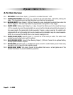
Violet Starter Output
Yellow Ignition 1 Output
Orange Accessory Output
Brown Ignition 2 Output/ACC/Starter2
Red +12V Battery Input #1 25 Amp.
Red +12V Battery Input #2 25 Amp.
Red +12V Battery Input #3
Green/White Brake Input(+)
Brown/White Horn Output (-)500mA
White Parking Light Output (+/- built-in relay)
White/Black Hood/Trunk Input (-)
Blue/Orange Remote Start output (-) When running
Black Ground
Black/Gray Tachometer Input
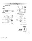
OVERIDE SW IN
LED OUT
Antenna
Green Lock output (-) 500mA.
Empty
Blue Unlock output (-) 500mA.
Control Unit
G-40RS
System Programming: Added Button 1 button 2
15. Trunk Release/ Horn Out Trunk Release Horn Output