


G 40RS - Page 9
2-Pin Blue Connector: Valet switch port. Mount switch where it is accessible from the driver’s position.
2-Pin Red Connector: LED port. Mount LED where it may be easily seen from either side of the vehicle.
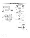
3-Pin White Door Lock Connector: Door lock port.
· BLUE WIRE - negative unlock output (-) 500mA.
· RED WIRE - (+) 100mA trigger output for optional plug-in door lock relay module,
· GREEN WIRE - negative lock output (-) 500mA.
5-Pin White Flat Connector: Antenna connector port.
Starter
Diagnostics
Starter doesn’t start and Parking Lights flash:
3 Times - Hood Trigger is active
4 Times - Brake Lights stay On
5 Times - Unit is in Valet (service) mode, and start is disabled.