


ALL SPECIFICATIONS ARE SUBJECT TO CHANGE WITHOUT NOTICE
#85-3905-01 07-10
1-800-669-9690
STOP LIGHT SWITCH BRACKET
INSTALLATION INSTRUCTIONS #751428
Failure to follow these instructions can result in
property damage, personal injury or even death.
WARNING
ROADMASTER, Inc. 6110 NE 127th Ave. Vancouver, WA 98682 1-800-669-9690 fax 360-735-9300 www.roadmasterinc.com
1. Start by attaching the stop light switch to the
bracket — follow the separate instructions in-
cluded with this kit.
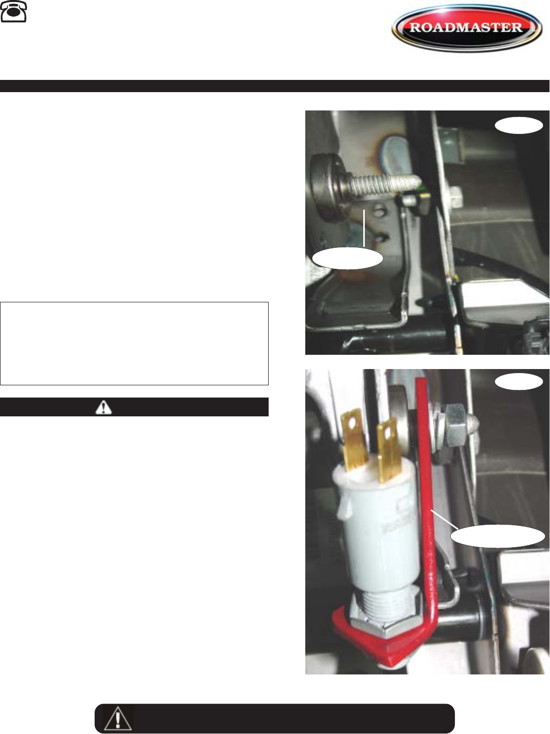
2. Locate the existing stud under the steering col-
umn (Fig.A).
3. Place the stop light switch bracket over the
existing stud and bolt into place using the sup-
plied 8mm x 1.25 nut, 8mm flat washer and 8mm
lock washer (Fig.B).
4. Now, adjust and wire the stop light switch —
follow the separate instructions included with this
kit.
When the installation is complete, verify that the
brake pedal retracts fully.
Unless they are installed correctly, the bracket and/
or other kit components may restrict or impede the
movement of the brake pedal — the brake pedal will not
retract fully.
If the brake pedal does not retract fully, the brakes
will be applied continuously, which may cause severe
tire and/or brake system damage, as well as other con-
sequential, non-warranty damage.
Failure to follow these instructions may cause prop-
erty damage, personal injury or even death.
WARNING
Fig.A
Fig.B
Stop Light Switch
Existing Stud
q
q
Parts List
(1) 8mm x 1.25 nut
(1) 8mm flat washer
(1) 8mm lock washer