


Chapter 6: Installation 6-11
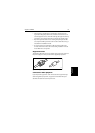
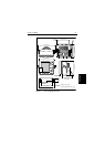
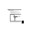
Mounting the Display
Unit
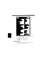
1. A clear, flat area of the following dimensions is required:
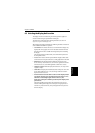
2. Unpack the flush-mounting kit.
3. Using the supplied template, trace out the display unit opening.
4. Drill a ½ in (12.7 mm) pilot hole in each corner of the cut-out area.
5. Using a suitable saw, cut along the inside edge of the cut-out line.
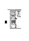
6. Remove the mounting bracket knobs and bracket from the display unit.
Make sure that the unit fits in the cut-out area.
If the optional screw fitting is required, drill four 3/16 in (5 mm) holes as
indicated on the template.
Screw the studs into the holes provided at the rear of the display.
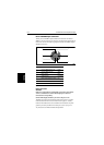
7. Connect the DC power cable, inter-unit cable, and any other accessory
cables to the display. Avoid tight bends in the cables.
8. Place the gasket on the unit and slide the unit into the panel cut-out.
9. Use the flush-mounting kit to secure the unit to the console.
Alternatively, place a spacer over each of the four studs and secure with
the thumb nuts.
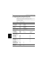
Display Width Height Depth behind Panel
7” Mono Display 9 in (230 mm) 8¼ in (210 mm) 6 in (152 mm)
7” Color Display 9 in (230 mm) 8¼ in (210 mm) 6.9 in (176 mm)
10.4” Color Display 11.75 in (300 mm) 11.6 in (295 mm) 6.4 in (162 mm)