


Installation Guidelines 165
data receiver and a transmitter together, e.g. a compass sensor transmit-
ting heading to a radar display.
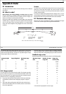
This information is passed in ‘sentences’, each of which has a three-letter
sentence identifier. It is therefore important when checking compatibility
between items that the same sentence identifiers are supported, e.g. VTG
carries Course and Speed Over Ground data, GLL carries latitude and longi-
tude, DBT carries water depth and MWV carries relative wind angle and
wind speed data.
D.3 Basic NMEA and RS-232 cabling principles
This section explains some of the basic principles involved with NMEA and
RS-232 electrical connections.
Knowledge of this information is not required to connect RayTech to your
peripheral instrumentation: however, it is provided for the advanced user
as a pertinent technical background.
NMEA basics
Most marine electronic devices that output data do so over NMEA ports.
These ports are known as a ‘balanced pair’, which means that the data
signal is carried over two wires (via an RS-422 electrical layer, in computer/
datacom terminology). The signal level is determined by calculating the
voltage difference between the two wires, hence the NMEA output signal
is called a Differential Data Signal (DDS). This DDS should not be confused
with Differential Global Positioning System (DGPS), which is a GPS system
error correction method.
DDS are designed to be error-resistant by keeping the positive and negative
leads close together for the entire cable run. This means that they both pick
up the same levels of noise, which is ultimately subtracted from the signal,
preserving the signal’s data integrity.
NMEA ports typically have four connections (two for each lead); Transmit
(positive/negative) and Receive (positive/negative). Some devices may use
a single-direction port, meaning that they can transmit or receive only.
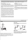
To connect one NMEA device to another:
1. Connect device A’s positive Transmit (Tx+) lead to device B’s positive
Receive (Rx+) lead.
2. Connect device A’s negative Transmit (Tx-) lead to device B’s negative
Receive (Rx-) lead.
IMPORTANT: When performing the above connection, make sure that you
connect the devices directly; DO NOT use the boat’s DC grounding circuit to
carry the Tx- or Rx- signal.
You may encounter a device that does not properly implement the NMEA
specification, and shares it’s Tx- lead with the device DC power ground
circuit. In this case, you must still run a cable directly between the Tx- and
Rx- leads as previously stated. DO NOT share the DC power ground circuit.
RS-232 basics
Most desktop and laptop computers have RS-232 ports. These ports use a 3
wire interface, in which the transmit and receive leads reference the same
signal ground. It is important not to confuse the RS-232 cable’s ground
with the boat’s power ground circuit. While the boat’s power ground may,
co-incidentally, be at the same level as the RS-232 signal ground, there is
no industry standard that requires this. Since the RS-232 transmit and
receive data signals reference a common signal ground to maintain their
integrity, you must connect the signal ground circuit directly between the
two RS-232 linked devices.
To wire one RS-232 device to another:
1. Connect device A’s Tx lead to device B’s Rx lead.
2. Connect device A’s Rx lead to device B’s Tx lead.
166 RayTech RNS V6.0 - Users Guide
3. Connect device A’s signal ground (SGnd) lead to device B’s SGnd lead.
RS-232 uses a common ground, which differs in electrical specification
form NMEA’s transmit/receive- pair arrangement. Because of these signal
level differences, the way you interconnect an RS-232 device and an NMEA
device varies with the application.
Note:
You may also encounter voltage differences when interconnecting
older RS-232/NMEA hardware. Take care to ensure the correct
connections.
To wire an RS-232 device to
provide input
to an NMEA device:
1. Connect the RS-232 device TX lead to the NMEA device RX+ lead.
2. Connect the RS-232 device SGnd lead to the NMEA device RX- lead.
To wire an RS-232 device to
provide and receive input
from
an NMEA device:
1. Connect the RS-232 device Tx lead to the NMEA device Rx+ lead.
2. Connect the RS-232 device Rx lead to the NMEA device Tx+ lead.
3. Connect the RS-232 device SGnd lead to the NMEA device Tx-
and
Rx-
leads.
There are some infrequent cases where binding the NMEA device Tx- and
Rx- leads together may cause difficulties. If you do encounter problems,
you will need to use an RS-232 to NMEA converter between the two
devices. A converter is required in rare cases, but is a good place to begin
troubleshooting if problems arise with the RS-232/NMEA connection. It
should be noted that the modern Furuno radar systems do require a
converter.
D.4 Circuit grounding issues
The most important issue in electrical connections is proper circuit
grounding. In addition to all of the other electrical gremlins that poor
grounding gives rise to, instrument signals are easily scrambled if they are
badly grounded. This results in erratic and unreliable displays. Installations
using both AC and DC current have a separate ground circuit for each. In
such cases, the checklist that follows will ensure that the ground circuits
are kept fully isolated:
• Always use isolating transformers or a separate power-inverter to run
PC, monitors and other sensitive electronic instruments or devices.
• Always use an isolating transformer with weather FAX audio cables.
• Always use an RS-232/NMEA converter with optical isolation on the
signal lines.
• Always use PC’s and other devices that are directly DC powered.
D.5 Cables and cable runs
When installing system cables consider the following:
• All cables should be adequately secured, protected from physical
damage and exposure to heat. Avoid running cables through bilges or
doorways, or close to moving or hot objects.
• Acute bends must be avoided.
• Where a cable passes through an exposed bulkhead or deckhead, a
watertight feed-through should be used.
• Secure cables in place using tie-wraps or lacing twine. Coil any extra
cable and tie it out of the way.
• Do not pull cables through a bulkhead or deckhead using a cord
attached to the connector. This could damage the connections.
D.6 Proper cable shielding
For all but the shortest length cable runs, data cables must be shielded to
prevent them from picking up electrical noise from other devices, and to
keep them from radiating potential interference. If you encounter a data