


Chapter 1: DSM Installation 15
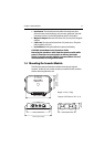
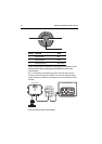
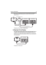
Transducer Connection
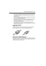
A 30 ft (10 m) cable is supplied with the transducer. This cable has a connector
plug (with an outer nut that you must attach) at one end for attaching to the
“T/D” connector on the sounder module. Optional extension cables are available.
CAUTION: Do Not Cut or Splice the Transducer Cable
• There is high voltage on the transducer cable. Splicing could
create a safety hazard.
• Cutting the transducer cable severely reduces sonar
performance. If the cable is cut, it must be replaced—it cannot
be repaired.
• Cutting the transducer cable will void the warranty and
invalidate the European CE mark.
DC Power Connection
The DSM300 is intended for use on boat’s DC power systems rated from 10.7 V to
32 V. The DSM30 is intended for use on boat’s DC power systems rated from 10.7
V to 18 V (12 volt systems only).
The power connection to the unit should be made at either the output of the
battery isolator switch or at a DC power distribution panel. Power should be fed
directly to the DSM via its own dedicated cable system and protected by a thermal
circuit breaker or fuse on the red (positive) wire that is installed close to the power
connection.
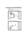
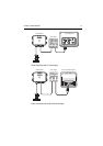
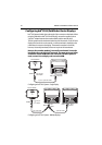
A10 ft (3 m) power cable is supplied with the unit. This cable has a connector plug
at one end for attaching to the “POWER” connector on the sounder module and
3 wires at the other end for connecting the power supply. The power cable may be
extended by up to 60 ft (20 m) using a wire gauge of AWG 12 or greater.
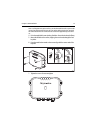
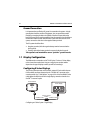
The RED wire must be connected to the feed from the positive (+) battery terminal
and the BLACK wire to the feed from the negative (–) battery terminal. The shield
wire (drain) should be connected to the boat’s RF ground. See “Ground
Connection” on page 18.
Install a quick blow 8 amp fuse on the red (positive) wire.
CAUTION: If the power connections are accidentally reversed the
system will not work. Use a multimeter to ensure that the input
power leads are connected for correct polarity.
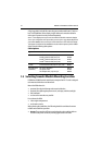
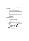
DC power is connected at the 3-pin POWER connector on the unit’s connector
panel. The connector (viewed from the outside) and pin functions are shown in
the following diagram and table.