


Chapter 6: Installation 6-5
Selecting the Display
Unit Location
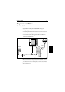
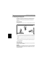
6.3 Selecting the Display Unit Location
The display unit can be mounted using the mounting bracket supplied, or
console mounted using the optional flush-mounting kit.
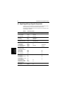
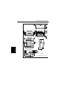
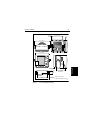
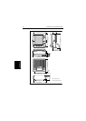
The dimensions of the display unit, including the bracket, are shown in
Figure 6-3, Figure 6-5 and Figure 6-4.
When planning the display installation, the following should be considered to
ensure reliable and trouble free operation:
• Convenience:The contrastand colorsseen on allcolor LCDdisplays vary
slightly with viewing angle; this is more noticeable on the left hand side.
Power the unit and select a suitable mounting location prior to installing
the display.
The mounting location should be easily accessible to allow operation of
the front panel controls.
• Access: There must be sufficient space behind the display to allow cable
connections to the rear panel connectors, avoiding tight bends in the cable.
• Interference: The selected location should be far enough away from
devices that may cause interference, such as motors, generators and radio
transmitter/receivers (see the EMC guidelines earlier in this section).
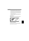
• Magnetic compass: Mount the display unit at least 3 ft (1m) away from a
magnetic compass.
• Cableruns:The displayunit mustbe locatednear aDC powersource.The
power cable supplied is 4.9 ft. (1.5m), but a longer cable can be used if
required: refer to Section 6.4.
• Environment:Do notrestrictairflow atthe rear ofthe displayunit;the
color display incorporates Cold Cathode Florescent Lamps (CCFL),
which have a reduced light output when the unit is very hot.
Ensure there is adequate ventilation, particularly if the display unit is
pod-mounted.
The display should be protected from physical damage and excessive
vibration. Although the display unit is waterproof, it is good practice to
mount it in a protected area away from prolonged and direct exposure to
rain and salt spray.