


Pacific Accessory Corporation - 1502 S. Santa Fe Street, Santa Ana, CA 92705
techsupport@pac-audio.com • www.pac-audio.com
Pacific Accessory Corporation
12-9-04
J1850
Class 2
VPW
Class 2
J1850
100011101111001001101100
1110 100 00 11011 01110 0110 0
Arbitration
EOD
CRC
100011101111001001101100
1110 100 00 11011 01110 0110 0
Class 2
Class 2
J1850
VCI-FRD1
Video Camera Interface Kit for Lincoln vehicles with Navigation
DISCLAIMER�
sustained in connection with the VCI-X. The manufacture and it’s distributors will not, nor will they authorize any representative or any other
individual to assume obligation or liability in relation to the VCI-X other than its replacement.
INSTALLATION:
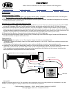
Connecting Navigation T-Harness:
1. Locate the Navigation unit in the vehicle. Use vehicle’s owners manual, if needed, to determine the location of the Navigation
unit. The Navigation unit is the CD or DVD ROM player, not the Headunit!
2. Unplug the factory 24 pin connector from the navigation unit and plug the T-Harness in between the Navigation unit and factory
wire harness as shown in picture below.
Wiring the VCI-X’s power, ground and switch input wires:
1. Connecting the power supply wires: Connect the VCI-X’s BLACK wire to the T-Harness’s black wire. Connect the VCI-X’s RED
wire to the T-Harness’s RED wire. The RED and BLACK wires are the ones coming out from the DC 12V side of the case.
2. Wire the VCI-X’s blue wire the T-Harness’s pink wire. The Pink wire supplies +12volts when the vehicle is put into reverse. If
there is no wire on the factory side of the wire harness where the pink wire is located, you will need to connect the VCI-X’s Blue
wire to the vehicle’s reverse wire manually. Note: The toggle switch manually triggers the video camera input, but will not be used for this
application. Leave the switch in the closed position so that the interface will work properly when vehicle is put into reverse.
3. Connect the Video Back-up Camera’s (optional) video output to the VCI-X’s video input.
4. After all connections have been verified, connect the 6 pin Molex plugs to the DB9 Molex plugs. Connect the DB9 harness to
the VCI-X interface and tighten the thumb screws.
Testing the VCI-X:
1. Turn the vehicle and navigation unit on. The navigation display should show normal information.
* If there is no image on the display, check for correct power connection on the VCI-X. Check to be sure Molex connectors are
connected securly.
* If the image on the display scrolls across the screen, make sure the Molex connectors are connected securely.
2. Temporarily put the vehicle into reverse being carefull not to back into anything or anyone. The display screen will change to the
video back-up camera mode. Put vehicle back to Park and the navigation display should show normal information.
*If the navigation map screen dissapears and you get a blank screen when the vehicle is put into reverse, check the video
back-up camera for proper power and video cable connection.
DB9 connector
NAVIGATION UNIT
Navigation Display
or
Display Control Unit
Red: +12 Switched
Black: Chassis Ground
Blue: +12 volt
trigger input
Pink: +12volt
reverse light
T-Harness
Video Input
Must connect at Navigation unit, not at the head unit!