


12
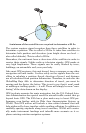
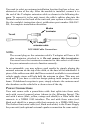
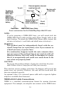
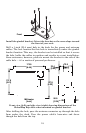
You need to select an antenna installation location that has a clear, un-
obstructed view of the sky. After the module is installed, connect it to
the end of the Y-adapter extension cable as shown in the following dia-
gram. To connect it to the unit, insert the cable's splitter plug into the
Network socket on the back of the unit and your system is ready to use.
See the module's instruction sheet, publication part number 988-0147-
981, for complete installation directions.
LGC-2000 Cable Connection.
NOTE:
The second plug on the extension cable’s Y-adapter will have a 60-
ohm terminator attached to it. Do not remove this terminator.
You must leave the terminator connected to this socket at all times
for your antenna/receiver to function correctly.
In an automobile, you may achieve good results by simply placing the
external antenna on the top of the dash, at the base of the windshield. A
piece of the rubber non-skid shelf liner material available in recreational
vehicle supply stores will help hold the antenna in place. This may not
work well if you have a cab-over design pickup truck camper or motor
home. If dashboard reception is poor, simply relocate the antenna mod-
ule elsewhere on the vehicle for a clearer view of the sky.
Power Connections
Your unit comes with a power/data cable that splits into three ends,
each with several exposed wires (shown in the following figure). The
end with 4 wires (blue, yellow, orange and shield) is a Data cable that
connects to a NMEA 0183 interface. The end with three wires (red,
black and shield) is a power cable that connects to a NMEA-2000 buss.
The thicker three-wire cable (red, black and white) is the Power Supply
for your unit (and optional external speaker connection for some units).
25' Y-adapter
extension cable
60-ohm
terminator
LGC-2000
To unit