


Ktm 690E and Smc instructions.doc 3528
KTM 690E and 690SMC 2008-09 mounting guidelines:
1. View all the pictures first, to get an idea of the concept of what is being described. Be sure you understand that the
black plastic shrouding around the key is going to need cutting in order for this kit to be mounted, a simple operation.
2. Note: pictures show silver parts to help you define how they go. Actual production parts are black.
3. This kit will raise the bars approximately 20mm, normally an improvement to this bike, but be aware before starting.
4. Remove the 4 bolts that hold your handlebars tight. Lay the bars forward out of the way.
5. Remove the stock lower perches from the triple clamp by removing the Allens and tapping on the perches.
6. Install the new SUB mount adaptor plate to the triple clamp using the (2) Allen bolts provided. There is a right and
wrong way to install this adaptor. The part numbers face forward and it bolts to the rear set of holes in the triple clamp.
Tighten these bolts to the Ktm specifications for handlebar mounts. Check your Ktm manual for those specs.
7. Install the stock lower perches to our Sub mount adapter using the stock Allen bolts, and remember the stock perches
can be reversed to achieve different bar positions. The most popular position is with the perches closest to the rider.
8. Install the bars and tighten the bolts so the gap between the upper and lower perch halves is equal.
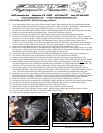
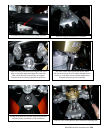
9. Remove the seat and both side panels. The side panels not only plug into the side but slide upward out of slots in order
to be removed. See the pictures on which bolts to remove. Remove the 2 bolts that hold the CDI box on the right side
and unplug the hose from the nipple, do not try to pull the nipple out of the plastic.
10. Using a pen, depress the center of the push pin retainer just behind the key switch to release that retaining device.
11. You can now fold the black side covers back out of the way in order to install the frame brackets.
12. Remove the seat bracket and just loosen the 2 key mounting bolts under the frame, to help align the key later.
13. Install the upper frame bracket plate so it drops over the key and the 3 fingers on the back align with the cross member.
14. Slide the bottom plate in under the frame rails, part number facing up, and engage the (2) bolts, but do not
tighten yet.
This bottom plate can only be installed one way with the open side of the “u” facing toward the front of the bike. The
idea here is to allow all these parts to find a comfortable, aligned seating point before tightening the bolts.
15. Once in place tighten the key mounting bolts first. Now move the top plate toward the front of the bike, almost
touching the head tube or wherever it aligns best with the key cylinder and frame rails. Tighten the top plate bolts to 6
ft lbs. The spacer between the top and lower plate will allow you to tighten the bolts without bowing the plates.
16. Tighten the (2) Allen bolts provided that hold the frame bracket tower to the top plate. This part is very close to the
head tube and the key cylinder. If interference exists, loosen all the bolts again and find the best spot before tightening.
17. Grease the tower pin and drop it in the tower. Keep it greased and free to float which insures proper alignment.
18. Install the stabilizer to the SUB mount after aligning the slot in the linkarm with the flats on the tower.
19. Turn the bars full lock left to right and be sure nothing is binding and that, the cables are free to move and not binding.
20. Start the bike and slowly turn the bars again to full lock to insure the cables are free to move and not binding.
21. Cut the plastic shrouds as per the photo guidelines until it fits the way you like it.
22. Reinstall seat bracket, side panels and CDI box in the reverse order that you took them off.
23. The stabilizer has 3 fully adjustable valving systems. Start with softer settings and work up to where you like it.
24. See your owner’s manual for “How to” adjust the stabilizer initial settings.
25. If you have any questions, please feel free to call us.
Remove screws here to remove left side panel
Remove here is you want to take the entire panel off