Ktm instructions.doc 5972
Ktm 2007 690 SM/SMC and 2008 690 Duke installation guidelines:
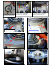
1. Each bike varies with regard to welds and gussets. Review the photos first to get the idea of what needs to be done.
2. These photos may not be your exact model but depict the concept of what must be done.
3. Block the front tire securely before removing the top triple clamp so the tire cannot move at all. See photos.
4. Support the rear tire also, just enough to keep tension on the front tire so the forks stay tight.
5. Warning: Once the triple clamp is loose, the forks can roll away from the bike AND it happens very quickly.
6. The main triple clamp nut adjusts the tension on the steering head bearings. Make note of its tension before
removing and do not over tighten the nut. It should be seated just enough to take the play out of the bearing..
7. The top of the gauge/light cluster is mounted to the top triple clamp. You have to take out 4 self tapping Phillips head
screws to remove the gauge pod. There is one connector on the back side of that and then it comes off. Then there are
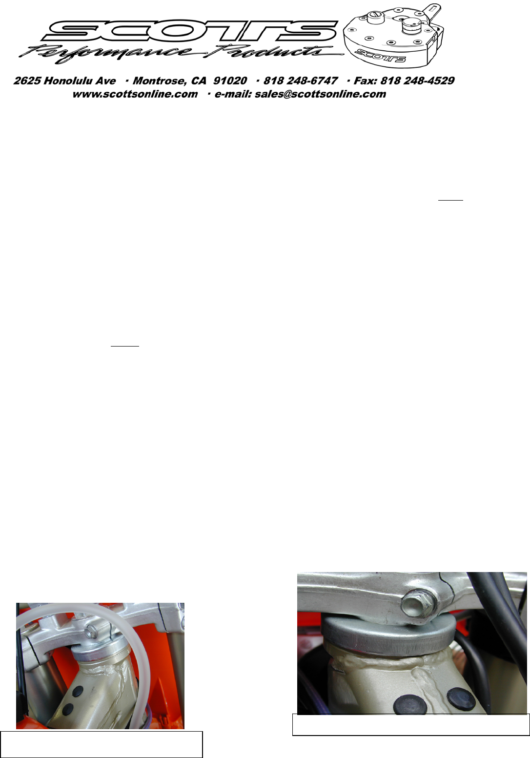
two bolts that need to come out with an 8mm wrench to free the top triple clamp.
8. Loosen the triple clamp pinch bolt under the main nut and forks pinch bolts and remove the top triple clamp, taking
note of how tight the main nut is, so you can re-tighten it to the exact amount. Remove the tin bearing shroud (cover)
and rubber seal making note of how the seal goes on, (lips face downward).
9. Grease your bearings while you have them exposed. (Keep the grease off the area where our frame bracket mounts!).
10. The goal is to allow the frame bracket to clamp cleanly and squarely around the upper half of the head tube.
11. Review your individual bike’s welding characteristics at the head tube. You’ll notice on the head tube there is a
“groove” machined 360 degrees around the head tube. Everything in or above this groove must be clean of welds or
slag. If this groove is visible all the way around and no welding slag has extended upward into or past this groove,
then you’re installation should
be easy. Any welds extending into or above this groove must be filed away, but without
changing the clamping area diameter. DO NOT file away the paint on the clamping area if possible. Spend a little
more time filing carefully and your bracket will stay tight.
12. Each bike seems to have not only different welds, but slightly different gussets. Evaluate your individual bike to
determine the best fit. The bracket must clamp squarely and cleanly to the area just above that groove and yet SIT
FLUSH all the way around the diameter of the head tube as per the photo in the lower right corner. Do not allow the
bracket to protrude above the seal seating surface. Use a flashlight to see up under the bracket where it’s hitting if it’s
not Flush. This bracket has clearance cut into it to clear the backbone of the frame.
13. Once it’s flush, align the frame bracket so the tower post is in the middle of the backbone of the frame and tighten the
pinch bolt on the frame bracket to 6-8 ft lbs. Double check the flush position after tightening the pinch bolt.
14. Install your stock seal and new shortened shroud (bearing cover), which is shorter than your stock tin shroud to allow
clearance. Try to avoid having the shroud make contact with the frame bracket but be as close a possible.
15. Re-install the triple clamp carefully, as now is the time when the forks will want walk away from the bike.
16. The shroud should pivot cleanly with the forks and have little or no contact with the frame bracket during turning.
17. Tighten the remaining triple clamp bolts and be sure the cables are routed as they were from the factory. Turn the bars
full lock, left to right, and verify the cables are not pinched or in harms way.
18. Install the handle bar clamp so it matches the handlebar position you specified during ordering. Ktm’s have 4
handlebar positions and the handle bar clamp provided fits only the position you ordered it for. See your owner’s
manual if you suspect something is mis-aligned. The manual explains how to verify this correct position.
19. Grease the tower pin and drop it in the tower. Keep it greased and free to float which insures proper alignment.
20. Install the stabilizer so the flats on the tower pin match the slot in the linkarm and tighten the 2 Allens for the damper.
21. See your owner’s manual for initial settings.
22. If you have any questions, please feel free to call us.
This example needs very little filing at the weld
This sample would need a lot of filing at the weld


