


ENGLISH
29
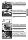
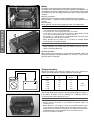
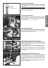
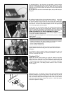
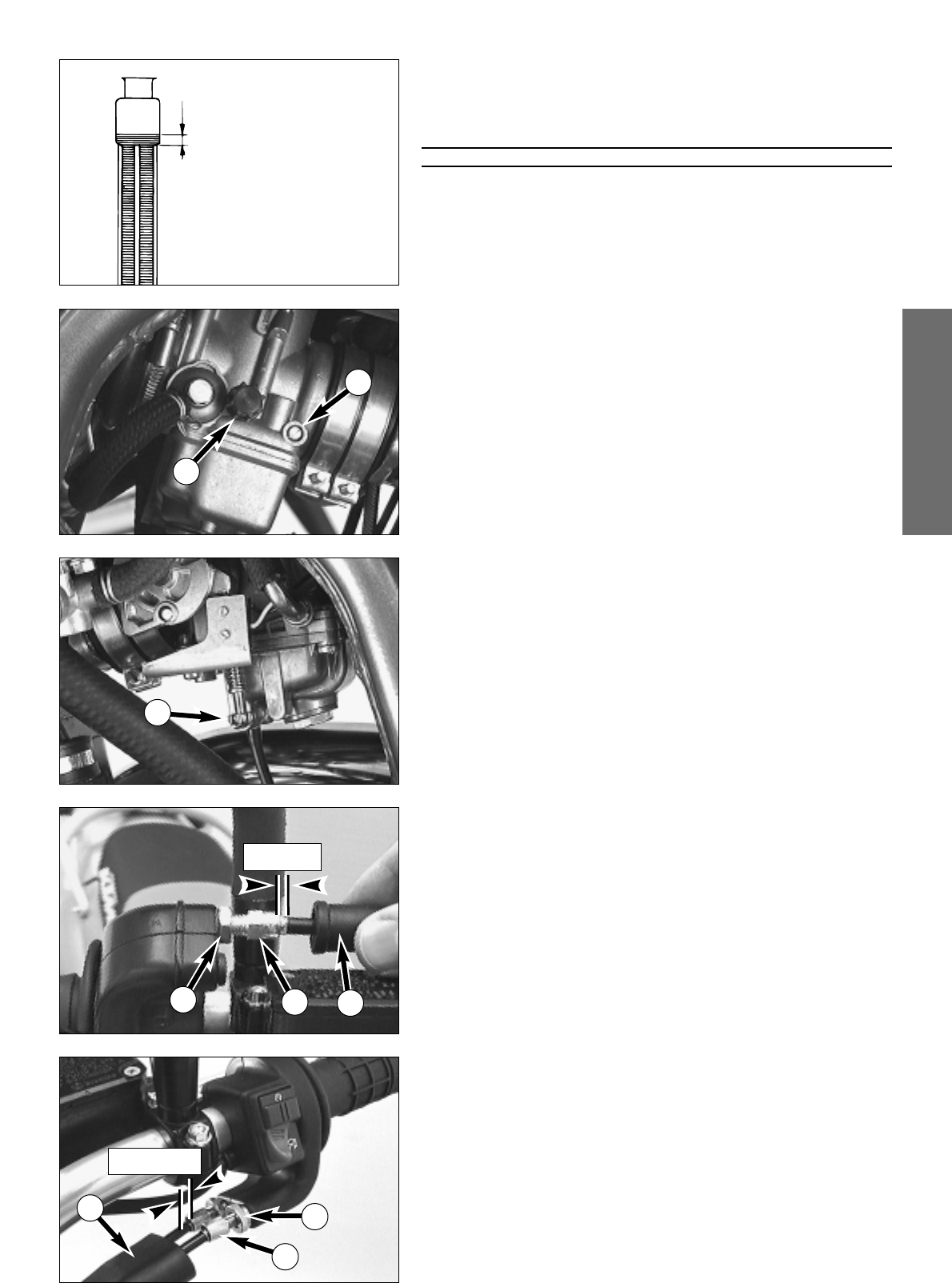
Checking the cooling liquid level
The cooling liquid should be 10 mm (0,4 in) above the cooling elements
when the engine is cold (cf. diagram). In the event of the cooling liquid
being drained, always fill the system before hand, then top off while the
engine is running.
ƽ
WARNING
ƽ
I
F POSSIBLE, ALWAYS CHECK LEVEL OF COOLING LIQUID WHEN ENGINE IS COLD. IF YOU
HAVE TO OPEN THE RADIATOR CAP WHEN ENGINE IS HOT
, USE A RAG TO COVER THE CAP
AND OPEN SLOWLY TO RELEASE PRESSURE
.
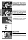
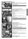
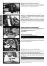
Adjust idling speed (Dell’Orto)*
The throttle stop screw 1 is used to adjust the basic position of the slide.
Turning in clockwise direction will increase the idling speed, turning in
counterclockwise direction will reduce the idling speed. Normal idling speed
1400 - 1500 rpm.
The mixture control screw
2 never should be changed.
Adjust idling speed (Mikuni)*
Use the adjusting screw
3
to adjust the basic position of the throttle valve
and, thus, the idle speed.Turning in clockwise direction will increase the
idling speed, turning in counterclockwise direction will reduce the idling
speed. Normal idling speed 1400 - 1500 rpm.
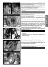
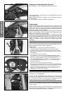
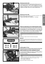
Adjusting the throttle cable (Dell’ Orto carburetor)*
There must always be a 3-5 mm (0.1-0.2 in) play in the throttle cable. To
check this, move back the protective cover
4 on the throttle grip. You must
be able to lift the outer covering of the cable 3-5 mm from the adjusting
screw
5, until resistance is felt.
To adjust, loosen the counter nut
6 and turn the adjusting screw accor-
dingly. Finally tighten counter nut and slide the protective cover back on.
To check the correctness of this setting, start the engine, turn the handlebar
left and right, in both cases as far as it will go. This must not cause any
changes in idling speed. Otherwise, you have to increase the backlash of
the throttle cable.
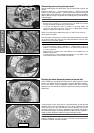
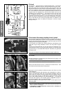
Adjusting the throttle cable (Mikuni carburetor)*
The throttle cables must at all times maintain a slack of 3-5 mm. To test
this, slide the protection cover
7
on the throttle grip backwards. You
should now be able to raise one of the cables so that its exterior covering is
3-5 mm from the adjustment screw
8
before resistance becomes noticea-
ble. Should a correction be necessary, this can be carried out at both adju-
sting screws.
To make the adjustment, loosen the counter screws
9
and turn the adju-
sting screws
8
correspondingly. Afterwards tighten the counter nuts and
slide on the protection cover.
3-5 mm
when engine is cold
10 mm
1
2
3
4
5
6
3-5 mm
7
8
9