


SERVICE INSTRUCTIONS
INSTRUCTIONS FOR MICRO SWITCH ADJUSTMENT
FOR AUTO TOP SIDE HEAD ACTUATOR
InstMSAdjTSHeadAct
9/08
www.keatingofchicago.com 1-800-KEATING
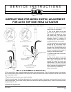
TOP SIDE HEAD DOWN
TOP SIDE HEAD UP
TOP SWITCH AND CAM
BOTTOM SWITCH AND CAM
(2) SWITCHES
MOUNTED AS SHOWN
TOP SWITCH SHOWN
MICRO SWITCH ACTUATORS
FOR TOP AND BOTTOM
SWITCHES SEE #3 − #8
(SET SCREWS)
SEE NOTES #3 & #4 FOR TOP MICRO
SWITCH AND NOTES #6 & #7 FOR
BOTTOM MICRO SWITCH
(TOP AND BOTTOM CAMS)
SEE NOTE #3 − #8
SEE NOTE #1 − #9
****NNOOTTEE TTHHEE TTOOPP AANNDD BBOOTTTTOOMM SSWWIITTCCHH AARREE AASSSSEEMMBBLLEEDD IINN LLIINNEE..****
1. Remove the limits switch black
plastic cover on the actuator.
2. Turn on the power on unit and
push the start button on the timer.
The actuator will extend the stroke
and lowers head. The motor must
stop and the stroke should stop
extending before it reaches its
mechanical stop. This movement is
controlled by the top micro switch.
3. If the motor fails to stop, manually
depress the top micro switch actua-
tor. This will disconnect power to the
actuator motor. Loosen the set screw
located on the top cam. Rotate the
top cam clockwise until the switch is
made (you should hear it click).
4. Tighten the set screw on the cam,
use blue locktite.
5. Turn on the power on unit and
push the start button on the timer
until it goes to the preset time. The
actuator will retract the stroke and
raise the head. The motor must stop
and the stroke should stop retracting
before it reaches its mechanical stop.
This movement is controlled by
bottom micro switch.
6. If the motor fails to stop, manually depress the bottom micro switch actuator. This will disconnect power to the actuator
motor. Loosen the set screw located on the bottom cam. Rotate the bottom cam counter clockwise, until the switch is made
(you should hear it click).
7. Tighten the set screw on the cam, use blue locktite.
8. Test the top side head. Verify the adjustments did not change the length of the stroke, thus preventing correct function
of the top side head. The top side cooking head must be able to reach the griddle plate. If it does not function properly
complete steps #2 - #7.
9. Reinstall the switches cover.
Tool needed: 2.5 mm Allen Wrench
Part # 037797
part # 037797