


128-7052
2 of 16
This Remote Start/Keyless Entry System is designed for use with Automatic Transmission Vehicles Only! The
unit provides wait to start input for glow plug pre-heat which will be used for all diesel applications. If this wire is
not connected, then the unit will remain in the Gasoline mode setting, which will crank the car when the RF signal
is received with no delay. Regardless of the vehicle, Gasoline or Diesel, for every installation, the vehicle MUST
HAVE a Tach Signal Input, and an Automatic Transmission.
INSTALLATION OF THE MAJOR COMPONENTS:
CONTROL MODULE:
Select a mounting location inside the passenger compartment (up behind the dashboard). The mounting location
selected must be within 24" of the ignition switch wiring harness to allow connection of the 6 pin main wiring harness.
Be certain that the chosen location will not interfere with proper operation of the vehicle. Avoid mounting the module
to or routing the wiring around the steering shaft/column, as the module or wiring may wrap around or block the
steering wheel preventing proper control of the vehicle. Secure the module in the chosen location using cable ties or
screws as necessary.
NOTE: Do Not Mount The Module In The Engine Compartment, as it is not waterproof.
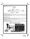
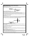
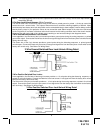
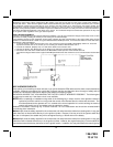
HOOD PIN SWITCH:
The hood pin switch included in this package is required for the safety shut down of the remote start unit. If the
vehicle is being worked on, this hood switch prevents the remote start activation even if the RF command to start is
issued. This hood pin switch MUST be installed in all applications. Failure to install the hood pin switch may result
in personal injury or property damage. Mount the hood pin switch in an area under the hood that is away from water
drain paths. If necessary, the included brackets may be used to move the hood pin switch away from rain gutters or
allow mounting to the firewall behind the hood seal. In either case the hood pin switch must be set up to allow the
hood to depress the switch at least 1/4" when the hood is closed and fully extended when the hood is opened. For
direct mounting, a 1/4" hole must be drilled. Carefully check behind the chosen location to insure the drill will not
penetrate any existing factory wiring or fluid lines. Drill a 1/4" hole in the desired location and thread the hood pin
switch into it using a 7/16" nut driver or deep well socket. If using the mounting bracket, first secure the bracket to the
desired location and secure the hood pin switch in the pre-threaded mounting bracket hole.
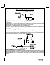
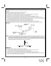
PROGRAM SWITCH:
Select a mounting location that is within reach of the ignition switch, as the program switch in combination with the
ignition switch will be used to program the selectable features of the system. It is suggested that the switch be
mounted to the lower dash panel in the driver's area. Inspect behind the chosen location to insure that adequate
clearance is allowed for the body of the switch, and also that the drill will not penetrate any existing factory wiring or
fluid lines. Drill a 1/4" hole in the desired location and mount the switch by passing it through the panel from the
underside. Secure the switch using the nut, star washer. Route the switch wires toward the control module.
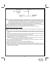
CONTROL SWITCH:
Select a mounting location known and accessible to the operator of the vehicle. A lower dash panel, kick panel, or
glove box is desirable. Inspect behind the chosen location to insure that adequate clearance is allowed for the body of
the switch, and also that the drill will not penetrate any existing factory wiring or fluid lines.
Drill a 1/4" hole in the desired location and mount the switch by passing it through the panel from the underside.
Secure the switch using the nut, star washer, and on/off faceplate. It is suggested that the switch be orientated to
allow the on position to be up toward the driver and the off position to be down or away from the driver. Route the
switch wires toward the control module. Place the RED rubber boot, included in the kit, over the switch handle to
differentiate this switch from the program switch.
The APS-55 is to be used in vehicles with AUTOMATIC TRANSMISSIONS only! Although this combination Keyless
Entry/Remote Start unit is a sophisticated system with many advanced features, IT MUST NOT be installed into a
vehicle with a manually operated transmission. Doing so may result in serious personal injury and property damage.
2