


128-7052
11 of 16
11
c. Immediately turn the ignition key OFF.
d. Hold the program switch ON, then start the vehicle using the ignition key.
e. When the unit senses the tach signal, the parking lights will begin to flash.
6. Release the program switch. The parking lights will turn on for 3 seconds to indicate that the tach signal is stored
and the unit is now out of the program mode.
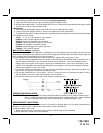
3. Diagnostics:
a. Be sure that programmable feature number #6 is set to the "Diagnostics On" mode.
b. Press and hold the program switch on, then turn the ignition key to the "ON" position.
c. The lights will flash and the number of flashes will indicate the reason for shutdown on the last remote start attempt.
The indications are as follows.
1 Flash 5, 10, 15, or 20, minute run timer expired.
2 Flashes Low or No tach signal received.
3 Flashes Positive or Negative input shut down.
4 Flashes Control switch was moved to "Off" position.
5 Flashes RF Shutdown command received.
6 Flashes High RPM signal over speed shut down.
7 Flashes Tach has NOT learned.
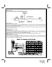
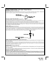
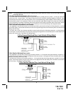
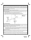
Multi Coil Pack Adapter: (Optional)
The multi coil pack adapter, (P/N 136B1400), is designed for use with vehicles that do not respond to single coil tach
programming. Although the tach resolution of this circuit is designed to interface direct with most vehicles, there may
be an occasion where the following circuit may be required.
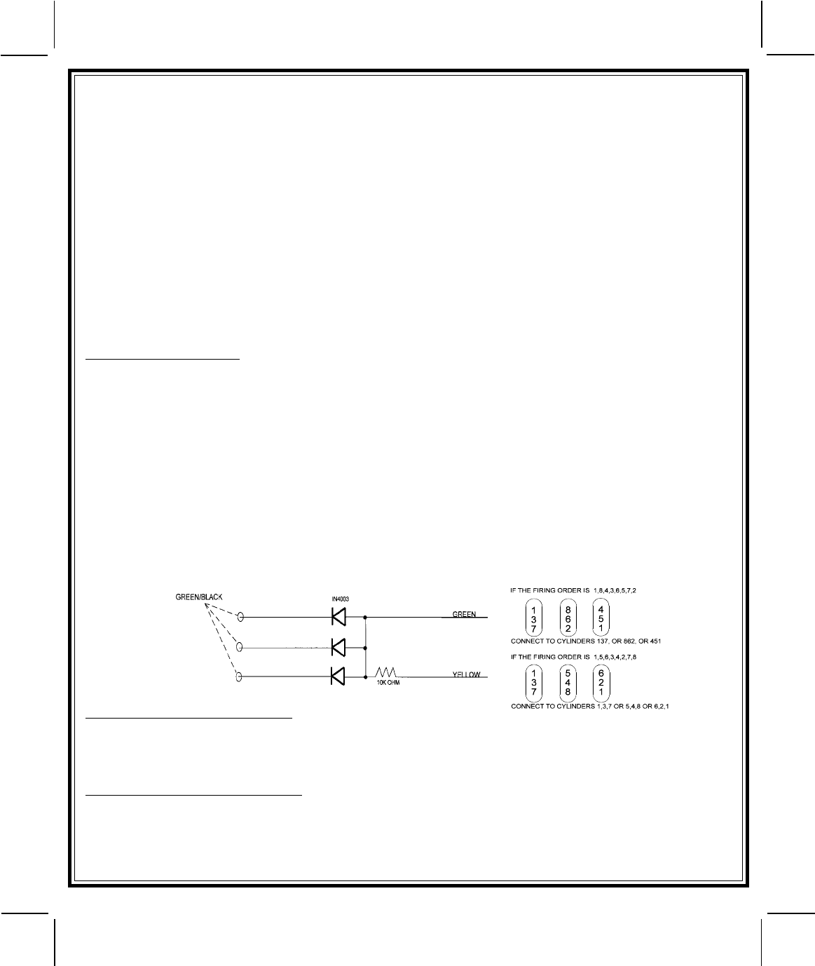
To use the adapter, the Green/Black wires must connect to the negative side of the ignition coil(s).
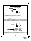
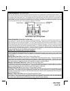
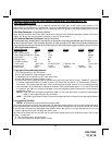
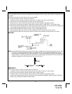
1. For vehicles utilizing independent coils per cylinder, connect the three Green/Black leads to alternate coils. To
achieve optimum performance the coil signals must be evenly distributed. This is accomplished by first
mapping out the firing order of the engine in groups of as indicated below. Draw a circle around any of the
columns. The Green/Black wires should be connected to the negative (-) terminal of the respective cylinder
number which appears in any of the circles.
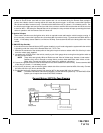
2. For vehicles utilizing 2 cylinder firing per coil pack, connect Green/Black to the tach side of each coil pack. For 8
cylinder, four coil systems, connect to any of the three coils.
3. Connect the Yellow wire to a +12 volt ignition 1 source. This wire will have +12 volts with the ignition in the on
and start position and have 0 volts with the ignition in the off position.
4. Connect the Green wire to the tach input of the Audiovox remote start unit.
TESTING YOUR INSTALLATION:
WARNING! The following procedure must be performed after the installation of an Audiovox Remote Start
Device. It is the responsibility of the installing technician to complete these tests. Failure to test the
unit in the following manner may result in personal injury, property damage, or both.
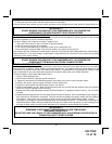
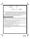
HOOD PIN SAFETY SHUT DOWN:
The intention of the hood pin safety shut down is to prevent the Remote Start unit from being activated while a
mechanic or vehicle owner is performing normal routine vehicle maintenance.
To test the integrity of this circuit:
1. With the driver's window in the down position, start the vehicle using the RF transmitter.
2.Reach inside the car and pull the hood release.