


128-6620A
3 of 8
Page 3
Dash Mounted LED:
A small LED is included that will serve as a visual indicator of the alarm status. It should be installed in the
dash, located where it can be easily seen from outside the vehicle, yet not be distracting to the driver.
Once a location has been selected, check behind the panel for wire routing access, and to confirm the drill
will not damage any existing components as it passes through the panel.
Drill a ¼" diameter hole, and pass the red and blue wires from the LED through the hole, from the front of the
panel. Firmly press the body of the LED into the hole until fully seated.
Valet Switch:
Select a mounting location for the switch that is easily accessible to the driver of the vehicle. The switch does
not have to be concealed, however, concealing the switch is always recommended, as this provides an even
higher level of security to the vehicle.
The valet switch can be mounted to the lower side of the dash by drilling a ¼" diameter hole in the selected
location.
Be sure to check behind the dash for adequate clearance for the body of the switch, and to confirm that the
drill will not damage any existing components as it passes through the dash. Route the two pin connector
toward the control module.
OPTIONAL Shock Sensor:
Select a solid mounting surface for the shock sensor on the firewall inside the passenger compartment, and
mount the sensor using the two screws provided. The shock sensor can also be secured to any fixed brace
behind the dash using tie straps.
Whichever mounting method is selected, make certain that the sensitivity adjustment is accessible for use
later in the installation.
WIRING THE SYSTEM
Large 8 Pin Edge Connector:
Red/White (5Amp) & Red Fused (15Amp) Wires: + 12 VDC CONSTANT BATTERY SOURCE
This wire controls the sensitivity of the voltage sensing circuit, which detects the turning on of an interior light
when a door is opened. It will also detect the switching on of parking or headlamps, and in many cases will
trigger the alarm when a thermostatically controlled electronic radiator cooling fan switches on.
When installing this system into vehicles with electronic "after fans", it is recommended you disable the
voltage sense circuit.
In voltage sensing applications, the closer to the battery that the red wire is connected, the less sensitive the
voltage sense circuitry will be. Moving this connection point to the fuse panel will increase the sensitivity, and
connecting to the courtesy lamp fuse in the vehicle will provide maximum sensitivity of the voltage sense
circuit. Be certain to set selectable feature # 7 to 1 chirp, Voltage Sense On.
When hardwiring the control module to pin switches at all entry points, the voltage sense circuit must be
disabled.
Orange Wire: 300 mA GROUND OUTPUT WHEN ARMED - N. C. STARTER DISABLE
This wire is provided to control the starter cut relay. Connect the orange wire to terminal 86 of the relay.
Connect relay terminal 85 to an ignition wire in the vehicle that is live when the key is in the on and crank
positions, and off when the key is in the off position. (This is where the yellow wire from the alarm should be
connected).
Cut the low current starter solenoid wire in the vehicle, and connect one side of the cut wire to relay terminal
87A. Connect the other side of the cut wire to relay terminal 30.
Note: This is a normally closed starter cut arrangement, and when power is removed from the
security system, the starter disable feature will not operate, allowing the vehicle to start.
Audiovox does not recommend using the Orange wire to interrupt anything but the starting
circuit of the vehicle.
Green w/ White trace Wire: Entry Illumination Ground Output
This wire provides a 30 second ground output (300 mA Max.) whenever the remote is used to disarm the
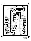
alarm or to unlock the doors and provides a continuous pulsed output whenever the alarm is triggered. This
wire should be connected to an external relay and wired to the vehicles interior entry lighting whenever the
optional Interior Illumination circuit is desired. See Wiring Diagram for details.