


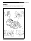
AJ-V8/5HP24
67
Transmission
Electrical Description
EM046
BLACK
16
9
14
6
5
2
3
1
10
13
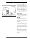
mistaken for an oil leak.
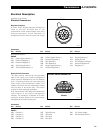
Electrical Connections
Bayonet Connector
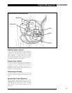
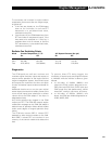
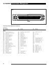
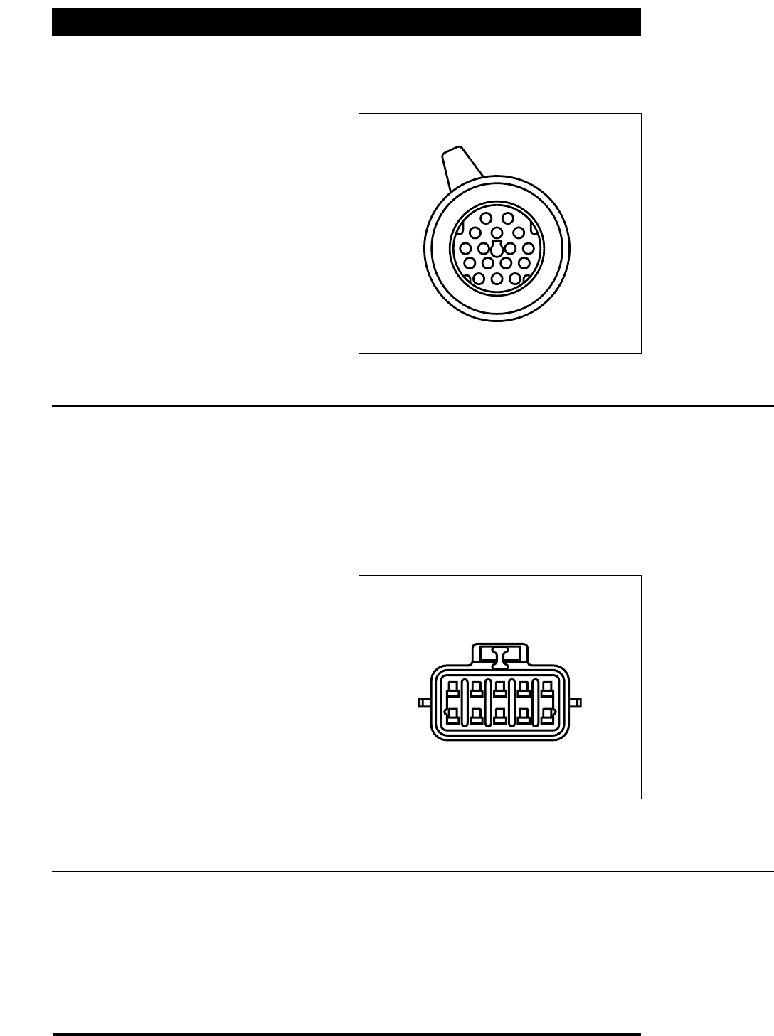
A round, 16-pin, bayonet electrical connector is
fitted at the rear left-hand side of the
transmission which communicates with the 5
pressure regulators, 3 shift solenoids, oil
temperature sensor and the input and output
Connector/
Pin Circuit Pin Circuit Pin Circuit
shaft speed sensors.
EM046
001 Output Speed Sensor (+)
002 Pressure Regulator 1
003 Pressure Regulator 2
004 Shift Solenoid Valve 3
005 Turbine Speed Sensor (+)
006 Turbine Speed Sensor (-)
007 Pressure Regulator 3
008 Shift Solenoid 1
009 Shift Solenoid 2
010 Output Speed Sensor (-)
011 Pressure Regulator 4
012 Solenoid Valves (+)
013 Analog Ground
014 Oil Temperature Sensor
015 Pressure Regulator 5
016 Regulator (+)
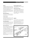
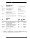
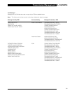
Rotary Switch Connector
The rotary switch, mounted on the right-hand
side of the casing, has a spline arrangement
which prevents misalignment with the selector
shaft. A locating pin and two bolts secure the
rotary switch to the transmission casing. This
locates the switch with the transmission casing
and the shaft in one place only. The switch
requires no other setting up procedure.
A 10-way connector with flying lead connects the
rotary switch to the engine management
harness. The connector is retained on a multi-
connector bracket bolted to the transmission
casing/torque converter housing joint.
BLACK
A
B
C
D
E
EM047
F
G
H
J
K
SOCKET
Connector/
Pin Circuit Pin Circuit Pin Circuit
EMO47
00A Position L1
00B Position L2
00C Position L3
00D Position L4
00E Digital Ground
00F Not Used
00G Not Used
00H Not Used
00J 12V Power Supply
00K Park & Neutral Switch
EM 046
BAYONET CONNECTOR
EM 047
ROTARY SWITCH CONNECTOR
307-024
307-023